2D Infiltration
The effect of infiltration and leakage at the surface zone in 2D models may be modelled with the MIKE+ 2D Overland module.
In MIKE+, the following infiltration Types are available via the 2D Infiltration editor:
- None
- Varying in Domain: Net infiltration rate varying spatially over the domain.
- Varying in Domain and Flow Dependent: Net infiltration rate varying spatially over the domain, calculated as a function of the water depth and the land cover.
- Varying in Domain and Time: Net infiltration rates that vary both spatially and temporally.
- Varying in Domain Using Capacity: Spatially-varying infiltration considering the capacity of the infiltration zone. Uses simplified infiltration model that calculates net infiltration using specified information on surface zone layer properties.
- Varying in Domain and Flow Dependent, Using Capacity: Varying infiltration considering the capacity of the infiltration zone, defined as a function of the water depth and the land cover. Uses simplified infiltration model that calculates net infiltration using specified information on surface zone layer properties.
More details on the various options and data requirements for the above-mentioned Infiltration Types are presented in succeeding sections.
Net Infiltration Rate
The most direct way of including infiltration in the 2D model is to specify net infiltration rate. When using a net infiltration rate, an unsaturated zone is not defined and thus has no capacity limits. The specified infiltration rates are in full effect as long as there is enough water in the grid cell/element.
Constant Infiltration with Capacity
It is however also possible to calculate the net infiltration rate by a simplified infiltration model.
The simplified model describes the infiltration from the free surface zone to the unsaturated zone, and the leakage from the unsaturated zone to the saturated zone.
The following parameters are specified for the simplified infiltration model:
- Infiltration rate. Flow between the free surface and infiltration zones.
- Leakage rate. Flow between saturated and unsaturated zones.
- Depth to/level of bottom of infiltration zone. The depth to or level of the bottom of the infiltration zone.
- Porosity of infiltration zone. Porosity (void fraction) of the infiltration zone.
- Initial water volume in Percentage of capacity (interval: 0-100 [%]) OR as fraction of the infiltration zone volume (interval: 0-porosity[()])
The model can account for a decreased storage capacity due to previous rainfall events. The model assumes the following:
- The unsaturated zone is modelled as an infiltration zone with constant porosity over the full depth of the zone.
- The infiltrated volume from the free surface zone and to the unsaturated zone is based on a constant flow rate
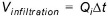 where \(Q_{i}\) is the prescribed infiltration rate.
 - The leaked volume from the unsaturated zone to the saturated zone is based on a constant flow rate
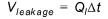 , where \(Q_{l}\)is the prescribed leakage rate.
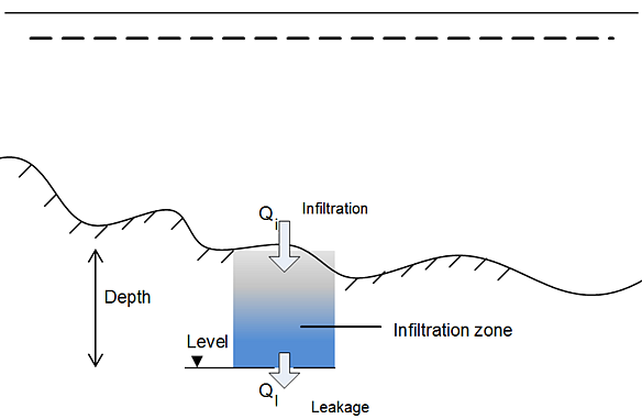
Figure: Definition of infiltration with storage and leakage: In the case of net infiltration, \(Q_{infiltration} = Q_{leakage}\), the model assumes an infinite storage volume in the infiltration zone.
The infiltrated flow volume cannot exceed the amount of water available in the free surface water zone nor the difference between the water capacity of the infiltration zone and the actual amount of water stored there. It is possible that the infiltration flow completely drains the free surface zone from water and thus creates a dried-out point in the 2-dimensional horizontal flow calculations. In case the infiltration is described by ‘Constant infiltration with capacity’ it is also possible that the infiltration zone becomes fully saturated so infiltration cannot take place (in which case \(Q_{i}\) is set to 0).
Varying in Domain
Data for infiltration that is ‘Varying in domain’ may be defined in the 2D overland model with:
- MIKE+ 2D infiltration layer
- Background layer of individual polygons
- 2D file
- Background layer of land Cover.
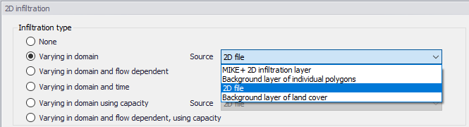
Figure: Options for specifying spatially-varying infiltration for the 2D overland model
MIKE+ 2D infiltration layer
This option requires definition of 2D infiltration polygon features on the Map.
One may use the Edit Features toolbox from the 2D Overland menu ribbon, or the Flooding Layer Editing Tools toolbar on the Map.
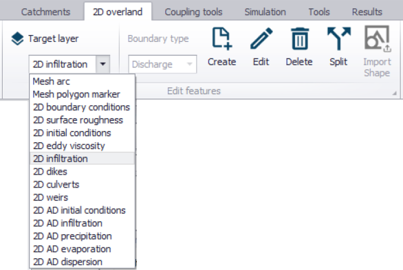
Figure: Edit 2D model layers on the Map using the Edit Features toolbar on the 2D Overland menu ribbon
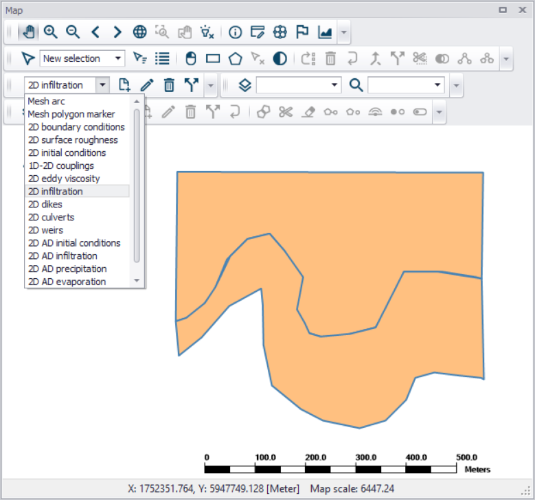
Figure: Create 2D infiltration polygon features on the Map using tools from the Flooding Layer Editing Tools toolbar
Define the 'Default infiltration rate' under the Infiltration Details section on the editor. This value will be used over areas in the domain for which infiltration parameters are not defined via the 2D Infiltration layer polygons on the Map.
The table under the Infiltration Details section on the editor lists information on each 2D infiltration polygon feature on the Map. Assign relevant infiltration properties for each feature on the table:
- Priority: Indicates the order with which values for overlapping features will be prioritized for use in the model.
- Apply: Check box allowing activation/deactivation of individual polygon features without deleting the polygon and its properties from the Map.
- Polygon ID: Unique 2D Infiltration polygon identifier.
- Infiltration rate: Infiltration rate value assigned to a polygon. The unit is shown in the header.
- Description: Optional text string for a free user description.
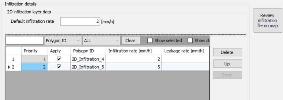
Figure: Fill-in parameters for 2D infiltration polygon features on the Map on the table under the ‘Infiltration details’ section. Use the ‘Review infiltration file on map’ button to view the configured 2D infiltration data layer on the Map.
Use the ‘Review infiltration file on map’ button to generate a 2D file from the infiltration configuration and view the generated file on the Map. The generated 2D file type depends on the defined 2D model type: *.DFS2 grid files for rectangular grid models, and *.DFSU unstructured files for flexible mesh models.
Background layer of individual polygons
When the space-varying infiltration input source is from a ‘Background Layer of individual polygons’, the ‘Infiltration details’ section on the 2D infiltration editor displays:
- Layer: The drop-down list is populated with background layers on the Map valid for use as 2D infiltration data. A layer is valid if it is of a *.TAB or *.SHP polygon type. Beside the Layer list, use the ellipsis button to browse to the location of other *.TAB or *.SHP polygon files.
- Infiltration rate item: A drop-down list of numerical attributes from the selected layer, which may be used as infiltration rate values.
- Unit: Select the desired units from the drop-down list of supported units for infiltration rate in the program.
- Default infiltration rate: This value will be used over areas in the domain for which infiltration parameters are not defined with the background layer polygons.
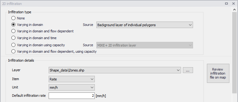
Figure: The program detects and offers valid Background Layers on the Map as sources of infiltration data. Use the ‘Review infiltration file on map’ button to view the configured 2D infiltration data layer on the Map.
Use the ‘Review infiltration file on map’ button to generate a 2D file from the infiltration configuration and view the generated file on the Map. The generated 2D file type depends on the defined 2D model type: *.DFS2 grid files for rectangular grid models, and *.DFSU unstructured files for flexible mesh models.
2D file
The ‘2D File’ option of specifying the source of spatially-varying infiltration input in the model, define the following in the editor:
- File: A drop-down list of valid 2D background layer files on the Map. A file is valid if it is a *.DFS2 or *.DFSU file with Item type = 'Infiltration', 'Seepage', or 'Recharge'. To the right side of the drop-down list is an ellipsis button that launches the 'Open a dfs file' dialog. Use the dialog to browse for a valid file. It filters on types '2D Grid file (*.DFS2)' or 'Unstructured data file (*.DFSU)', and has a drop-down list for selecting the Item to load. The 'View' button opens the selected 2D file for viewing/editing. It launches the Grid Editor if a *.DFS2 file has been selected in the editor. If a *.DFSU file has been selected, it opens the file using the Data Manager.
- Infiltration rate item: Non-editable text box displaying the selected Item from the loaded file.
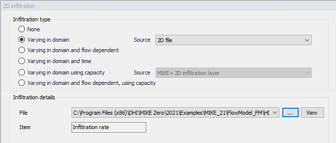
Figure: Point to a 2D infiltration file under the Infiltration details section on the editor
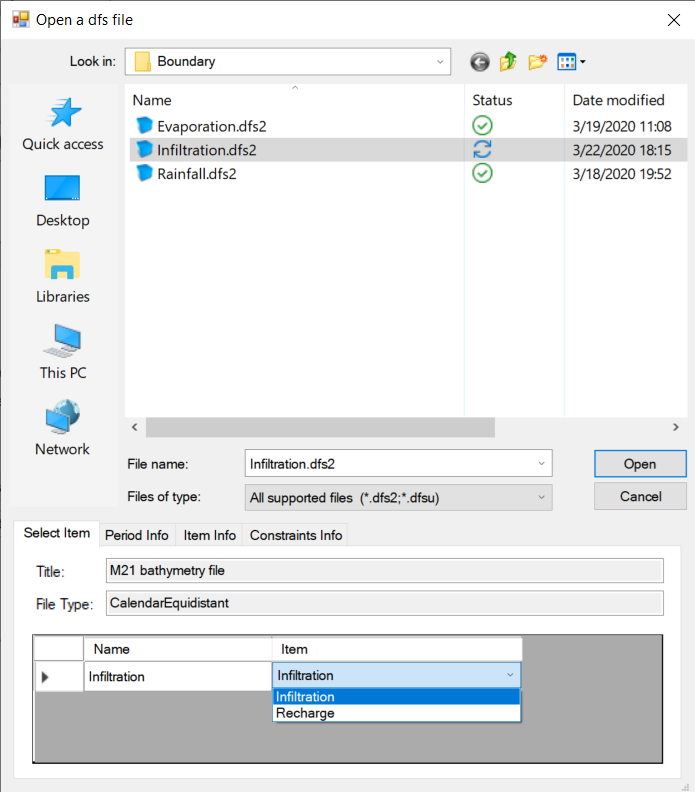
Figure: Browse to the valid 2D file via the ‘Open a dfs file’ dialog
Background layer of land Cover
The 'Background layer of land cover' option allows defining the net infiltration rate as a function of land cover, i.e. per land cover type. A polygon layer must be selected to define the land cover, in which the polygons are grouped by category (land cover type). Three types of file format can be used for defining the land cover types:
- Shape file
- DFS2 or DFSU file
- XYZ file
For XYZ files and shape files, the land cover zones are defined as the closed region within a number of polygons. For dfs files, the zones are defined by a map identifying the location of the different zones. Each land cover type is identified by an integer number larger than zero. If an element from the 2D domain belongs to more than one polygon in the XYZ file or the shape file, the information from the last polygon read from the file is applied. If there are overlapping zones with the road zones (from the 2D infrastructures editor), the priority is first given to the road zones.
For dfs files, the value should be zero in areas with no local infiltration zone in a dfs file.
For XYZ files, the data in the file must be formatted as ASCII text in five columns with the two first columns giving the x-and y-coordinates of the points. The third column represents connectivity. The connectivity column is used to define arcs. All points along an arc - except the last point - shall have a connectivity value of 1 and the last point shall have a connectivity value of 0. The fourth column contains the z-value at the point, which is unused for land cover layers. Finally, the fifth column contains the zone number, corresponding to the land cover type.
In the 'Land cover layer' section, the following needs to be specified:
- Layer: The source layer defining the land cover zones
- Item: For a shape file or dfs file, this is the attribute or item in the file containing the integer number, used to identify the land cover type each polygon belongs to.
- Map projection: For a XYZ file, this is the map projection in which the XY coordinates in the file are defined.
In the 'Infiltration rate' table, the net infiltration rate is specified for each of the zones. The list of zones is made of the list of land cover types plus the list of road zones eventually selected in the 2D infrastructures editor. The land cover ID for these zones is editable. A default rate must also be supplied, which is applied in areas not covered by any of the previous zones.
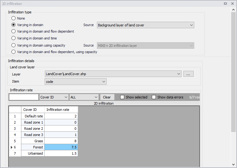
Figure: Defining infiltration rates for land cover types
Varying in Domain and Flow Dependent
The 'Varying in domain and flow dependent' option allows defining the net infiltration rate as a function of the water depth on the surface, and also as a function of land cover, i.e. per land cover type. A polygon layer must be selected to define the land cover, in which the polygons are grouped by category (land cover type). A curve defining the relationship between the water depth and the infiltration rate must then be selected for each land cover type. Three types of file format can be used for defining the land cover types:
- Shape file
- DFS2 or DFSU file
- XYZ file
For XYZ files and shape files, the land cover zones are defined as the closed region within a number of polygons. For dfs files, the zones are defined by a map identifying the location of the different zones. Each land cover type is identified by an integer number larger than zero. If an element from the 2D domain belongs to more than one polygon in the XYZ file or the shape file, the information from the last polygon read from the file is applied. If there are overlapping zones with the road zones (from the 2D infrastructures editor), the priority is first given to the road zones.
For dfs files, the value should be zero in areas with no local infiltration zone in a dfs file.
For XYZ files, the data in the file must be formatted as ASCII text in five columns with the two first columns giving the x-and y-coordinates of the points. The third column represents connectivity. The connectivity column is used to define arcs. All points along an arc - except the last point - shall have a connectivity value of 1 and the last point shall have a connectivity value of 0. The fourth column contains the z-value at the point, which is unused for land cover layers. Finally, the fifth column contains the zone number, corresponding to the land cover type.
In the 'Land cover layer' section, the following needs to be specified:
- Layer: The source layer defining the land cover zones
- Item: For a shape file or dfs file, this is the attribute or item in the file containing the integer number, used to identify the land cover type each polygon belongs to.
- Map projection: For a XYZ file, this is the map projection in which the XY coordinates in the file are defined.
In the 'Infiltration rate' table, the Infiltration Curve defining the relationship between the water depth and the net infiltration rate must be selected for each zone. The list of zones is made of the list of land cover types plus the list of road zones eventually selected in the 2D infrastructures editor. The land cover ID for these zones is editable. A default curve must also be supplied, which is applied in areas not covered by any of the previous zones.
Valid curves are curves with the type 'Depth dependent infiltration'. The 'Create curves' button can be used to create a curve (in the Curves and Relations editor) with some default values for each of the zones.
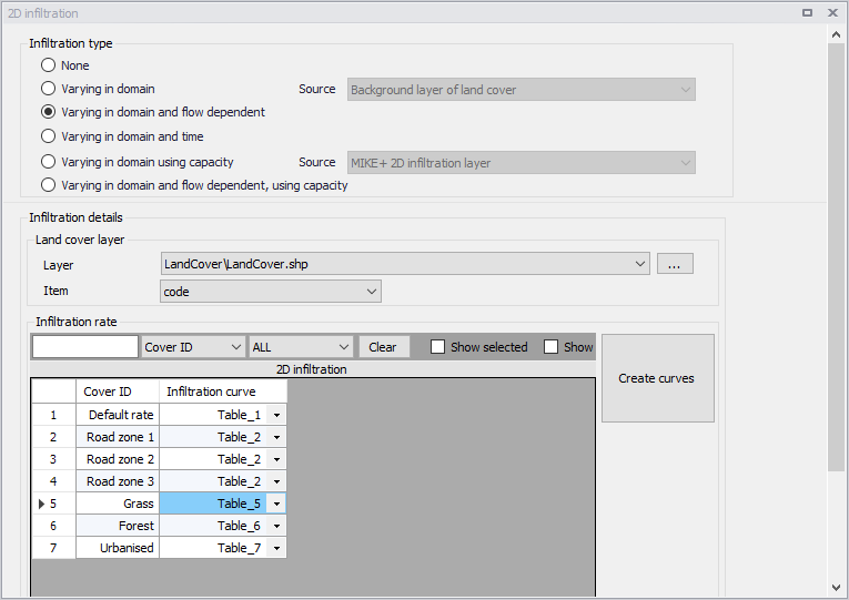
Figure: Defining depth-dependent infiltration curves for land cover types
Varying in Domain and Time
Infiltration data that varies with time as well as domain is defined as a time-varying 2D file in the 2D overland model.
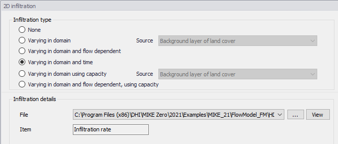
Figure: Browse to a time-varying 2D file for input infiltration data that varies in domain and time
- File: A drop-down list of valid 2D background layer files on the Map. A file is valid if it is a time-varying *.DFS2 or *.DFSU file with Item type = 'Infiltration', 'Seepage', or 'Recharge' The ellipsis button launches the 'Open a dfs file' dialog that is used to locate a valid time-varying 2D file. The dialog filters on types '2D Grid file (*.DFS2)' or 'Unstructured data file (*.DFSU)', and has a drop-down list for Items that may be loaded. The 'View' button opens the selected time-varying 2D file for viewing/editing. It launches the Grid Editor if a *.DFS2 file has been selected in the editor. If a *.DFSU file has been selected, it opens the file using the Data Manager.
- Infiltration rate item: Non-editable text box displaying the selected Item from the loaded file.
Varying in Domain Using Capacity
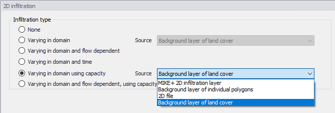
Figure: Source options for 2D Infiltration data of ‘Varying in domain using capacity’ type
Data for infiltration that is ‘Varying in domain using capacity’ may be defined in the 2D model with the following sources (figure above):
- MIKE+ 2D infiltration layer: 2D infiltration polygons defined on the Map in MIKE+.
- Background layer of individual polygons: Pre-loaded polygon background layer on the Map.
- 2D file: Existing infiltration 2D file (*.DFS2 or *.DFSU types)
- Background layer of land cover: Pre-loaded polygon background layer defining the type of land cover
More details on configuration requirements for each source type are described in succeeding sections.
MIKE+ 2D infiltration layer
This option requires the definition of 2D infiltration polygon features on the Map.
One may use the Edit Features toolbox from the 2D Overland menu ribbon, or the Flooding Layer Editing Tools toolbar on the Map, to create 2D infiltration polygons. Records for each polygon feature are listed in a table on the 2D Infiltration editor.
Under the ‘Infiltration Details’ section, specify:
- Bottom level of infiltration zone defined from:
- Depth below ground level
- Specified level
- Initial water volume in infiltration zone defined from:
- Percentage of the capacity
- Percentage of the infiltration zone volume
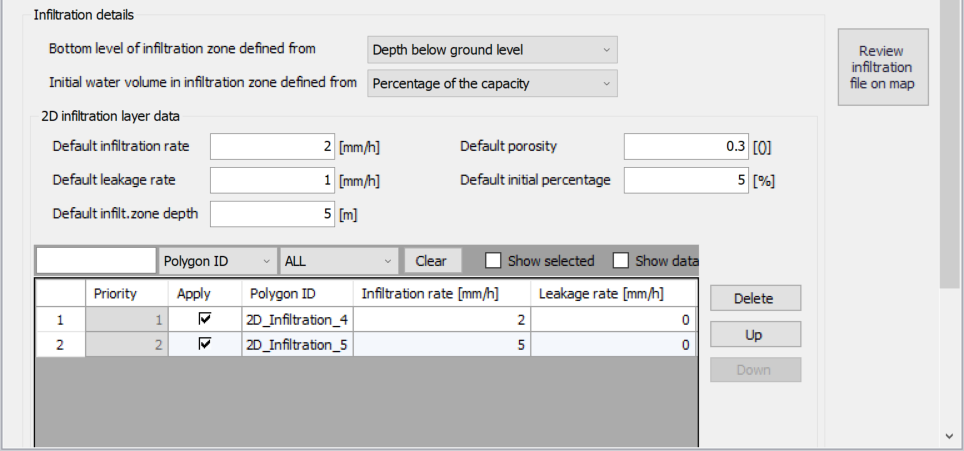
Figure: Configure 2D infiltration data layer properties under the Infiltration Details section on the editor. The table lists 2D infiltration polygons drawn on the Map.
Under the '2D infiltration layer data' section, define:
- Default infiltration rate: Flow between the free surface and infiltration zones.
- Default leakage rate: Flow between saturated and unsaturated zones.
- Default infilt. zone depth/Default infilt. zone level: ‘Default infilt. zone depth’ when 'Bottom level of infiltration zone defined from’ = 'Depth below ground level'. ‘Default infilt. zone level’ when 'Bottom level of infiltration zone defined from’ = 'Specified level'.
- Default porosity: Porosity (void fraction) of the infiltration zone.
- Default initial percentage: Initial water volume in Percentage of capacity (interval: 0-100 [%]) OR as fraction of the infiltration zone volume (interval: 0-porosity[()])
These default values are used over areas not covered by the defined 2D infiltration layer polygon features on the Map.
The table listing the features for the 2D infiltration layer has the following data columns:
- Infiltration rate: Flow between the free surface and infiltration zones.
- Leakage rate: Flow between saturated and unsaturated zones.
- Infilt. zone depth/Infilt. zone level: The depth to or level of the bottom of the infiltration zone indicating its extent. When ‘Bottom level of infiltration defined from’ = 'Depth below ground level', the header name is 'Infilt. zone depth'. When ‘Bottom level of infiltration defined from’ = 'Specified level', the header name is 'Infilt. zone level'
- Porosity: Porosity (void fraction) of the infiltration zone.
- Initial percentage: Initial percentage of the capacity or fraction of the infiltration zone volume (depending on the selected option in the drop-down list 'Initial water volume in infiltration zone defined from'). Initial water volume in Percentage of capacity (interval: 0-100 [%]) OR as fraction of the infiltration zone volume (interval: 0-porosity[()])
Define desired values for the above parameters on the table for each 2D infiltration polygon.
Use the ‘Review infiltration file on map’ button to generate a 2D file from the infiltration configuration and view the generated file on the Map. The generated 2D file type depends on the defined 2D model type: *.DFS2 grid files for rectangular grid models, and *.DFSU unstructured files for flexible mesh models.
Background layer of individual polygons
When a background layer shall be the source of the 2D infiltration (Varying in domain using capacity) input, the corresponding polygon data layer must be loaded onto the Map as a Background Layer.
Under the ‘Infiltration Details’ section, specify:
- Bottom level of infiltration zone defined from:
- Depth below ground level
- Specified level
- Initial water volume in infiltration zone defined from:
- Percentage of the capacity
- Percentage of the infiltration zone volume
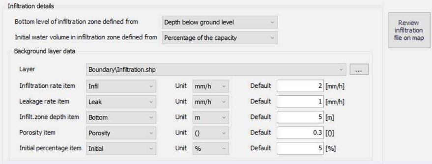
Figure: Use a polygon background layer with numerical attributes for infiltration zone parameters
Define the following parameters under the ‘Background layer data' section:
- Layer: A drop-down list showing valid background layers loaded on the Map. Valid layers are *.TAB or *.SHP polygon types. The ellipsis button is used to browse to an external polygon *.TAB or *.SHP file.
- Below is a list of parameters that must be defined based on the loaded Layer:
- Infiltration rate item: Flow between the free surface and infiltration zones.
- Leakage rate item: Flow between saturated and unsaturated zones.
- Infilt. zone depth/level item: The label uses the word ‘depth’ if ‘Bottom level of infiltration zone defined from’ = ‘Depth below ground level'. Otherwise, the label indicates ‘level’ if ‘Bottom level of infiltration zone defined from’ = ‘Specified level'.
- Porosity item: Porosity (void fraction) of the infiltration zone.
- Initial percentage item: Initial water volume in Percentage of capacity (interval: 0-100 [%]) OR as fraction of the infiltration zone volume (interval: 0-porosity[()])
Select the appropriate numerical attribute from the loaded layer file for each parameter using the drop-down list. Each drop-down list is populated with the full list of (numerical) attributes from the selected layer.
To the right of the parameter input boxes are 'Default' value input boxes. These values are used over areas not covered by the input file layer features.
Use the ‘Review infiltration file on map’ button to generate a 2D file from the infiltration configuration and view the generated file on the Map. The generated 2D file type depends on the defined 2D model type: *.DFS2 grid files for rectangular grid models, and *.DFSU unstructured files for flexible mesh models.
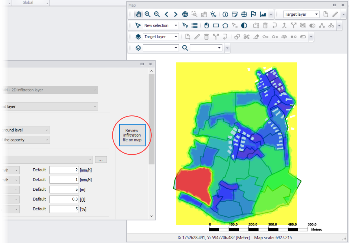
Figure: 2D infiltration data layer (.dfsu) generated from configuration using the ‘Review infiltration file on map’ functionality
2D file
This source option requires specifying a spatially-varying 2D infiltration input file containing 5 data items describing infiltration zone properties.
Under the ‘Infiltration Details’ section, specify:
- Bottom level of infiltration zone defined from:
- Depth below ground level
- Specified level
- Initial water volume in infiltration zone defined from:
- Percentage of the capacity
- Percentage of the infiltration zone volume
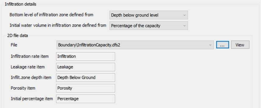
Figure: Define a 2D file containing data items on infiltration zone properties
Specify the 2D File under the ‘2D file data' section. The ‘File’ input box has a drop-down list of valid files loaded as background layers on the Map. Valid files are *.DFS2 or *.DFSU files containing the following data items:
- Infiltration, Seepage, or Recharge: Flow between the free surface and infiltration zones.
- Leakage: Flow between saturated and unsaturated zones.
- Bottom level of infiltration zone as:
- Depth Below Ground: If ‘Bottom level of infiltration zone defined from’ = 'Depth below ground level'
- Elevation: If ‘Bottom level of infiltration zone defined from’ = 'Specified level'.
- Porosity, Porosity coefficient, Dimensionless factor, or Specific yield. Porosity (void fraction) of the infiltration zone.
- Initial water volume in infiltration zone: Initial water volume in Percentage of capacity OR as fraction of the infiltration zone volume
- Percentage or Fraction: (interval: 0-100 [%]). If ‘Initial water volume in infiltration zone define from’ = 'Percentage of the capacity'.
- Volumetric Water Content: (interval: 0-porosity[()]). If ‘Initial water volume in infiltration zone define from’ = 'Percentage of the infiltration zone volume'.
To the right of the File drop-down list, use the ellipsis button to browse to an external 2D file. The 'Open a dfs file' dialog filters on types '2D Grid file (*.DFS2)' or 'Unstructured data file (*.DFSU)', and has a drop-down list from where the item to load may be selected.
The 'View' button opens the specified 2D file for viewing/editing. It launches the Grid Editor if a *.DFS2 file has been selected in the editor. If a *.DFSU file has been selected, it opens the file using the Data Manager.
Below the File input box are non-editable text boxes displaying the relevant Items in the specified file corresponding to the:
- Infiltration rate item: Flow between the free surface and infiltration zones.
- Leakage rate item: Flow between saturated and unsaturated zones.
- Infilt. zone depth/level item: The label indicates ‘depth’ if ‘Bottom level of infiltration zone defined from’= 'Depth below ground level'. Otherwise, the label uses ‘level’ if ‘Bottom level of infiltration zone defined from’= ‘Specified level'.
- Porosity item: Porosity (void fraction) of the infiltration zone.
- Initial percentage item: Initial water volume in Percentage of capacity (interval: 0-100 [%]) OR as fraction of the infiltration zone volume (interval: 0-porosity[()])
Background layer of land cover
The 'Background layer of land cover' option allows defining the infiltration capacity as a function of land cover, i.e. per land cover type. A polygon layer must be selected to define the land cover, in which the polygons are grouped by category (land cover type). Three types of file format can be used for defining the land cover types:
- Shape file
- DFS2 or DFSU file
- XYZ file
For XYZ files and shape files, the land cover zones are defined as the closed region within a number of polygons. For dfs files, the zones are defined by a map identifying the location of the different zones. Each land cover type is identified by an integer number larger than zero. If an element from the 2D domain belongs to more than one polygon in the XYZ file or the shape file, the information from the last polygon read from the file is applied. If there are overlapping zones with the road zones (from the 2D infrastructures editor), the priority is first given to the road zones.
For dfs files, the value should be zero in areas with no local infiltration zone in a dfs file.
For XYZ files, the data in the file must be formatted as ASCII text in five columns with the two first columns giving the x-and y-coordinates of the points. The third column represents connectivity. The connectivity column is used to define arcs. All points along an arc - except the last point - shall have a connectivity value of 1 and the last point shall have a connectivity value of 0. The fourth column contains the z-value at the point, which is unused for land cover layers. Finally, the fifth column contains the zone number, corresponding to the land cover type.
Under the 'Infiltration Details' section, specify:
- Bottom level of infiltration zone defined from:
- Depth below ground level
- Specified level
- Initial water volume in infiltration zone defined from:
- Percentage of the capacity
- Percentage of the infiltration zone volume
Under the 'Land cover layer' section the following needs to be specified:
- Layer: The source layer defining the land cover zones
- Item: For a shape file or dfs file, this is the attribute or item in the file containing the integer number, used to identify the land cover type each polygon belongs to.
- Map projection: For a XYZ file, this is the map projection in which the XY coordinates in the file are defined.
In the 'Infiltration rate' table, the infiltration capacity is specified for each of the zones. The list of zones is made of the list of land cover types plus the list of road zones eventually selected in the 2D infrastructures editor. The land cover ID for these zones is editable. A default rate must also be supplied, which is applied in areas not covered by any of the previous zones. For each zone, the following data need to be provided:
- Infiltration rate: Flow between the free surface and infiltration zones.
- Leakage rate: Flow between saturated and unsaturated zones.
- Infilt. zone depth/Infilt. zone level: The depth to or level of the bottom of the infiltration zone indicating its extent. When 'Bottom level of infiltration defined from' = 'Depth below ground level', the header name is 'Infilt. zone depth'. When 'Bottom level of infiltration defined from' = 'Specified level', the header name is 'Infilt. zone level'
- Porosity: Porosity (void fraction) of the infiltration zone.
- Initial percentage: Initial percentage of the capacity or fraction of the infiltration zone volume (depending on the selected option in the dropdown list 'Initial water volume in infiltration zone defined from'). Initial water volume in Percentage of capacity (interval: 0-100 [%]) OR as fraction of the infiltration zone volume (interval: 0-porosity[()]).
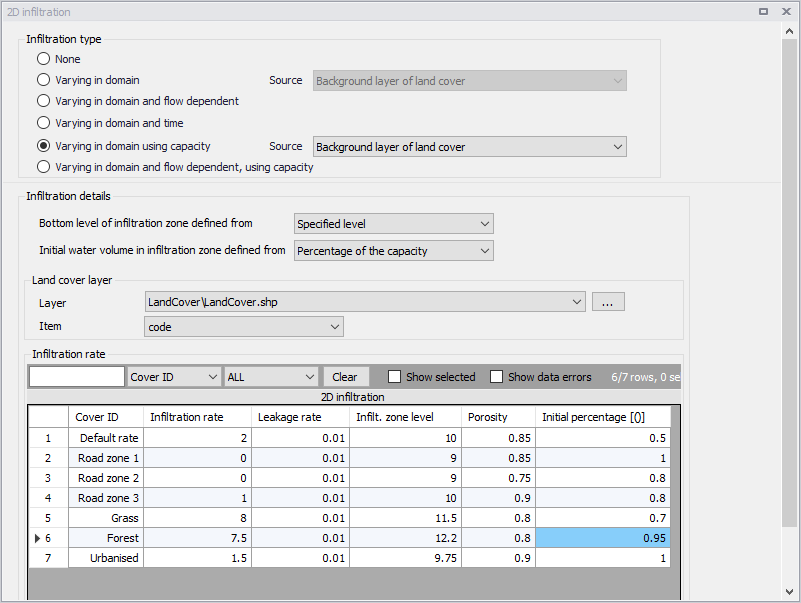
Figure: Defining infiltration capacity for land cover zones
Varying in Domain and Flow Dependent, Using Capacity
The 'Varying in domain and flow dependent, using capacity' option allows defining the infiltration capacity as a function of the water depth on the surface, and also as a function of land cover, i.e. per land cover type. A polygon layer must be selected to define the land cover, in which the polygons are grouped by category (land cover type). A curve defining the relationship between the water depth and the infiltration rate must then be selected for each land cover type. Three types of file format can be used for defining the land cover types:
- Shape file
- DFS2 or DFSU file
- XYZ file.
For XYZ files and shape files, the land cover zones are defined as the closed region within a number of polygons. For dfs files, the zones are defined by a map identifying the location of the different zones. Each land cover type is identified by an integer number larger than zero. If an element from the 2D domain belongs to more than one polygon in the XYZ file or the shape file, the information from the last polygon read from the file is applied. If there are overlapping zones with the road zones (from the 2D infrastructures editor), the priority is first given to the road zones.
For dfs files, the value should be zero in areas with no local infiltration zone in a dfs file.
For XYZ files, the data in the file must be formatted as ASCII text in five columns with the two first columns giving the x-and y-coordinates of the points. The third column represents connectivity. The connectivity column is used to define arcs. All points along an arc - except the last point - shall have a connectivity value of 1 and the last point shall have a connectivity value of 0. The fourth column contains the z-value at the point, which is unused for land cover layers. Finally, the fifth column contains the zone number, corresponding to the land cover type.
Under the 'Infiltration Details' section, specify:
- Bottom level of infiltration zone defined from:
- Depth below ground level
- Specified level
- Initial water volume in infiltration zone defined from:
- Percentage of the capacity
- Percentage of the infiltration zone volume
In the 'Land cover layer' section, the following needs to be specified:
- Layer: The source layer defining the land cover zones
- Item: For a shape file or dfs file, this is the attribute or item in the file containing the integer number, used to identify the land cover type each polygon belongs to.
- Map projection: For a XYZ file, this is the map projection in which the XY coordinates in the file are defined.
In the 'Infiltration rate' table, the infiltration capacity is specified for each of the zones. The list of zones is made of the list of land cover types plus the list of road zones eventually selected in the 2D infrastructures editor. The land cover ID for these zones is editable. A default curve must also be supplied, which is applied in areas not covered by any of the previous zones. For each zone, the following data need to be provided:
- Infiltration curve: The curve defining the relationship between the water depth and the infiltration rate defined in the Curves and Relations editor.
- Leakage rate: Flow between saturated and unsaturated zones.
- Infilt. zone depth/Infilt. zone level: The depth to or level of the bottom of the infiltration zone indicating its extent. When 'Bottom level of infiltration defined from' = 'Depth below ground level', the header name is 'Infilt. zone depth'. When 'Bottom level of infiltration defined from' = 'Specified level', the header name is 'Infilt. zone level'
- Porosity: Porosity (void fraction) of the infiltration zone.
- Initial percentage: Initial percentage of the capacity or fraction of the infiltration zone volume (depending on the selected option in the dropdown list 'Initial water volume in infiltration zone defined from'). Initial water volume in Percentage of capacity (interval: 0-100 [%]) OR as fraction of the infiltration zone volume (interval: 0-porosity[()]).
Valid curves are curves with the type 'Depth dependent infiltration'. The 'Create curves' button can be used to create a curve with some default values for each of the zones.