Auto Connection Tool
When overland flow paths have been digitized and snapped to a correct alignment, the overland flow links have to be connected to each other (overland to overland) or connections have to be made between the overland flow network and the subsurface network.
The tool can generate both connections between the same type of network and connections between two different types of network. A network can be defined as i.e. Stormwater, Combined Sewer, Sanitary Sewer or a user-defined network type. A user-defined network could be Overland Flow network (OF) or Rising Main (RM). User-defined network types are set in the ‘Pipes and canals table’ under the “Description” tab and “Network type” (select the “…” to obtain the Status code editor).
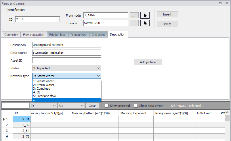
Figure: Editing network type
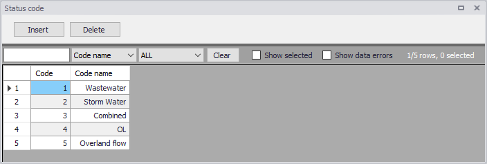
Figure: Status Code editor
The nodes in the model must be provided with the appropriate network type before proceeding to set up the connections.
A connection can be a weir, orifice or curb-inlet for a MOUSE network, and a weir or orifice for a SWMM network. Connections between an overland flow network and a subsurface network are usually either orifices or curb-inlets while connections between two overland flow networks are usually weirs. The connective structure is created according to the direction specified in the tool. When connecting an overland flow network with a subsurface network, the direction should be specified from the overland network to the subsurface network.
A user-specified search radius is used around the nodes from the network listed under “From nodes” to control where connections can be made. If the two different networks are connected, the connection will be made to the closest node with the type of the “To nodes”. If identical networks are connected, then connections will be made between all nodes within the search radius that are not already connected.
The structures are created with an invert level according to the network, but other parameters for the individual structures must be set manually. If two different networks are connected, the default invert for the structure will come from the invert of the upstream node. If two identical networks are connected, the default invert for the structure will be the maximum of the upstream and downstream node inverts. An offset for the invert can be specified in the tool. It is recommended to insert a small offset of i.e. 0.05 m between overland flow networks and subsurface networks to ensure that flow is not always occurring through the connection.
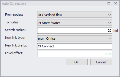
Figure: Auto Connection Tool
An example from a 1D/1D model is provided in the figure below where the blue network represents the stormwater network and the red network represents the overland flow network. The overland flow network is connected to the stormwater network by orifices. The overland flow network elements are connected together at junctions by weirs.
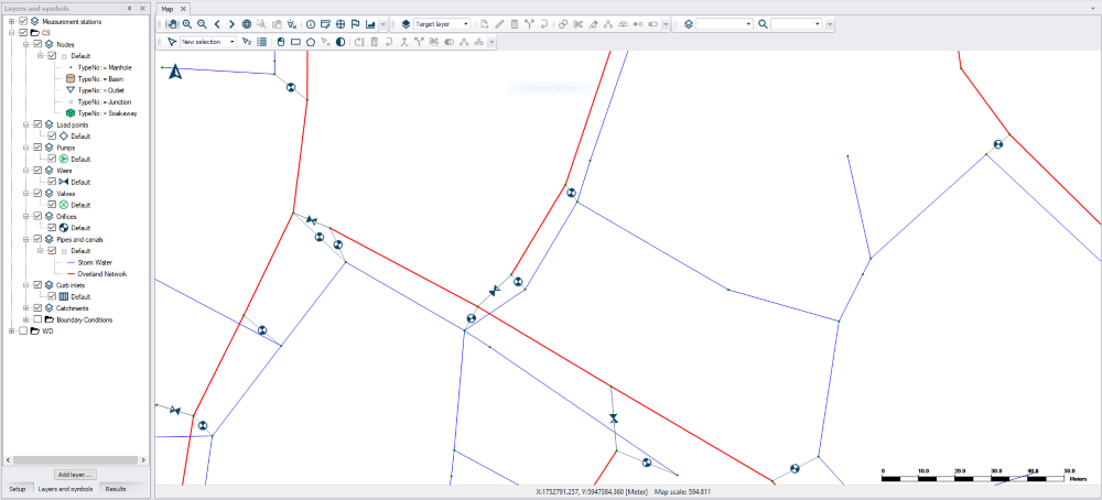
Figure: Example of connections
The tool will try to make connections for selected nodes, and if no node is selected, connections will be attempted for all nodes according to the specifications.