Simulation Setup
MIKE+ simulations are started from the 'Simulation specifications' section. Individual simulations can be configured and run from the 'Simulation setup' editor, each e.g. using different modules, simulation periods or time setp settings.
Once configured, individual simulations can be executed in batch mode from the Batch simulation editor, applying an automatic and sequential launch of several simulation setups.
Info
Simulations can also be executed without opening the editor, through command lines. Refer to Section Predefined export from command lines for more information.
The following sections describe the configuration of individual simulation setups. The 'Simulation setup' editor has several tabs, which are shown depending on the active features and modules for the project:
- General: Includes general parameters, such as definition of the simulation period, selection of simulation types, and free text description of the simulation setup.
- Catchments: Includes parameters specific for Runoff simulation.
- HD: Includes parameters specific for HD simulation.
- AD and WQ: Includes parameters specific for network AD simulation and MIKE ECO Lab.
- LTS: Includes parameters specific for Network LTS simulation.
- Results: Includes specification of results (output) to be generated by the simulation.
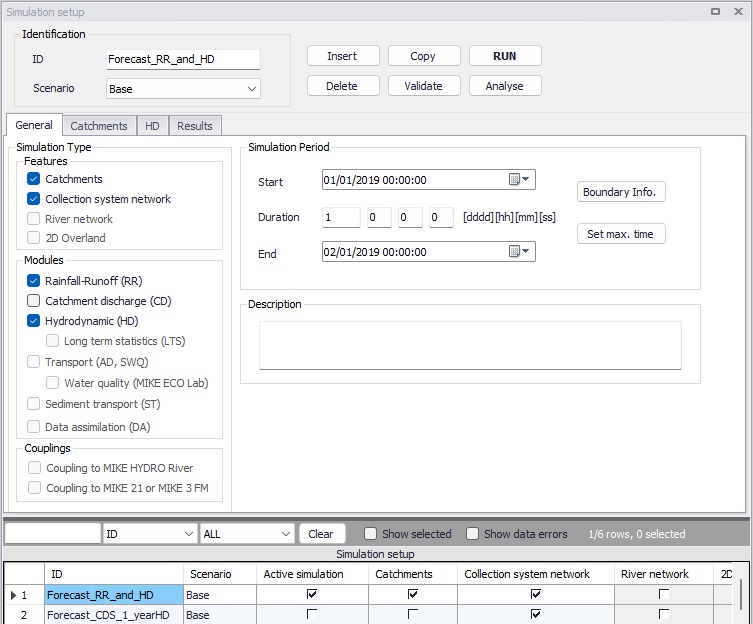
Figure: The Simulation Setup editor
The table at the bottom of the editor contains an 'Active simulation' check box, which flags a simulation setup as the one in use by default, for instance when starting the simulation using the Ctrl+R shortcut or using a command line. Only one simulation at a time may be set as "Active".
Identification
The 'Identification' group at the top contains the following attributes:
- ID: User-specified ID of simulation. This ID will be reflected in the name of result files.
- Scenario: Dropdown menu for selecting ID of Scenario for the simulation.
- Event ID: An 'Event ID' may be associated with the simulation, to use only boundary conditions associated with this event (or not associated with any event). The value 'No event filter' indicates that all active boundary conditions will be used in the simulation (unless their 'Apply' check box is unticked). If some boundary conditions (from editors 'Boundary conditions', 'Load points' and/or '2D boundary conditions') are associated with a specific event ID in their 'Description' tab, this event ID can be selected in the simulation setup. When such a specific event ID is selected, the simulation runs with only the boundary conditions defined with this event ID as well as with those not associated with any event, i.e. set to 'Default (any event)'. The use of events is a simple alternative to the use of boundary alternatives with the Scenario manager.
The following buttons are also located at the top of the editor with the Identification group:
‘Insert’ button
Inserts a new record in the Simulation Setup editor with a default ID.
‘Copy’ button
Duplicates an existing (currently active) simulation setup record.
‘Delete’ button
Deletes a currently active simulation record.
‘RUN’ button
Triggers export of the current simulation job and execution of the simulation within MIKE+.
‘Run detached’ button
Triggers export of the current simulation job and execution of the simulation in a separate window. It is possible to run only one simulation at a time within the MIKE+ window, therefore this button offers an alternative which allows to run multiple simulations at the same time in different windows.
'Validate' button
MIKE+ offers an automatic validation, checking for data errors on-the-fly while data are edited in the various editors. For river and/or CS networks, the ‘Validate’ button offers a complementary option to collectively check the consistency of the MIKE+ project data through the validation of the entire simulation setup. Press the 'Validate' button to open the validation window:
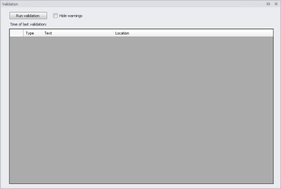
Figure: The Simulation Validation window
The validation applies to the simulation currently “selected” in the 'Simulation setup' editor. From this window, press the 'Run validation' button to start the data validation and see the list of warnings and errors in the table. The validation time depends on the database size, number of active modules and number of errors found.
A description of the warning or error is included in the 'Text' column in the list. The description usually indicates the data type or editor in which the error should be corrected.
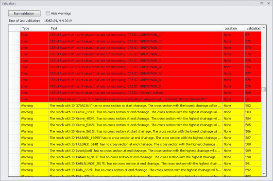
Figure: The validation list indicates whether an item is an Error (highlighted in red) or a Warning (highlighted in yellow)
It is possible to activate the 'Hide warnings' option to only show errors without warnings in the list.
Note
The comprehensive validation performed by the 'Validate' function only supports river and/or CS networks, but not 2D overland models. For 2D overland models, validation errors are solely reported in the 2D overland editors.
'Analyse' button
This button opens a tool that can be used to find elements of a river or CS network that may be contributing to instabilities during an HD simulation. The tool produces a list of h-points ranked according to one of the three following criteria, all ranked from smallest to largest:
- Time step required to achieve a specified stability criterion
- Surface area
- Length
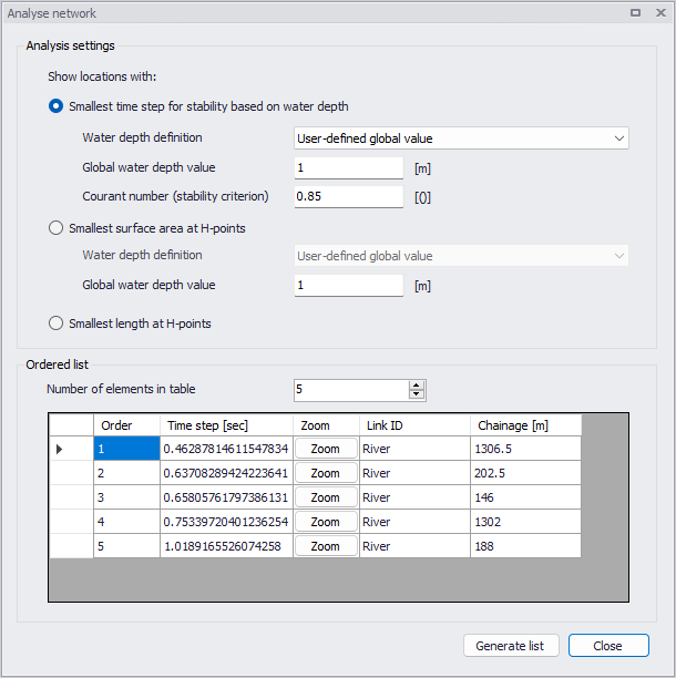
Figure: The Analyse network tool
More information about the three options is provided below.
Time step required to achieve a specified stability criterion
When using this option, the tool finds the time step needed to achieve a specified Courant number for each h-point. This option can be used to find an appropriate time step for a stable simulation or identify parts of the model network that should be streamlined to enable a stable simulation at a longer time step.
Because the Courant number evaluation depends on the depth of water, a depth definition must be provided. Four options are available:
- User-defined global value: single value applied throughout network.
- Full-running pipe or river (min. of markers 1 and 3): for rivers, this option uses the minimum of markers 1 and 3 as water level in each cross section. A full-running pipe is used for collection system modelling.
- Full-running pipe or river (min. of markers 1 and 3): for rivers, this option uses the minimum of markers 4 and 5. If markers 4 and 5 are not defined, then the minimum of markers 1 and 3 is used. A full-running pipe is used for collection system modelling.
- Initial conditions: Water depth definitions are taken from the initial conditions specification.
Surface area
Under this option, the tool computes the surface area associated with each h-point, in other words the surface area from the upstream Q-point to the downstream Q-point (or from the calculation point to the nearest upstream or downstream Q-point, if the calculation point is located at the start or end of a river branch).
A depth is needed to compute a surface area. The same four options are available as for 'Time step required to achieve a specified stability criterion'.
For rivers, the area is calculated assuming a constant width equal to the width of the cross-section at the specified depth. For collection system modelling, the area is calculated using a very small width corresponding to a pipe that is almost full. The flow area criterion is not particularly useful for analysis of pipes.
Length
Under this option, the tool computes the length associated with each h-point, in other words the length from the upstream Q-point to the downstream Q-point (or from the calculation point to the nearest upstream or downstream Q-point, if the calculation point is located at the start or end of a river).
Note
The 'Analyse' function only supports river and/or CS networks, but not 2D overland models.
General
The 'General' tab includes parameters relevant for the entire simulation setup. The following parameters are specified in the General tab:
- Simulation type
- Simulation period
- Description
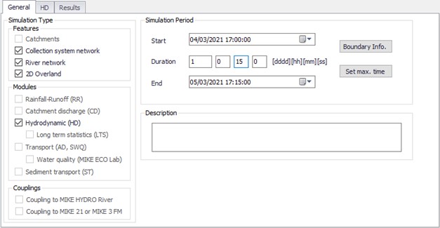
Figure: The Simulation Setup editor General tab
An overview of the editor fields and corresponding database attributes is provided in the table below.
| Edit field | Description | Used or required by simulations | Field name in datastructure |
|---|---|---|---|
| Catchments | Activates catchment-related simulation types | Yes | Enable_Catchment |
| Collection system network | Activates CS related simulation type | Yes | Enable_CS |
| River network | Activates river related simulation type | Yes | Enable_River |
| 2D Overland | Activates 2D related simulation types | Yes | Enable_2DOverland |
| Rainfall-Runoff (RR) | Activates runoff simulation | Yes | Enable_RR |
| Catchment Discharge (CD) | Activates catchment discharge computations | Yes | Enable_CD |
| Hydrodynamic (HD) | Activates HD simulations for CS, Rivers and/or 2D overland | Yes | Enable_HD |
| Long Term Statistics (LTS) | Activates LTS simulation | Yes | Enable_LTS |
| Transport (AD, SWQ) | Activates AD simulations for CS, Rivers and/or 2D overland and/or SWQ simulations for catchments | Yes | Enable_AD |
| Water quality (MIKE ECO Lab | Activates MIKE ECO Lab simulations for CS, Rivers and/or 2D overland | Yes | Enable_ECOLAB |
| Sediment Transport (ST) | Activates CS network sediment transport simulation | Yes | Enable_ST |
| Data Assimilation (DA) | Activates DA network update simulation | Yes | Enable_DA |
| Coupling to MIKE HYDRO River | Activates coupling to MIKE HYDRO River. HD coupling is always activated. AD coupling is activated if Transport (AD,SWQ) module is also activated (see note below). | Yes | Enable_MHRiver_ Coupling |
| Coupling to MIKE 21 or MIKE 3 FM | Activates coupling to MIKE 21 FM or MIKE 3 FM. HD coupling is always activated. AD coupling is activated if Transport (AD,SWQ) module is also activated (see note below). | Yes | Enable_M21FM_ Coupling |
| Start | Specifies start date and time for the simulation. | Yes | ComputationBegin |
| Duration | Displays the duration of the simulation in days, hours. minutes and seconds. Automatically adjusted based on Start and End time/date. May be edited, adjusting End date/time accordingly. | Yes | - |
| End | Specifies end date and time for the simulation. Adjusted automatically according to user's specification of duration. | Yes | ComputationEnd |
| Description | Free text description of the simulation setup | Optional | Description |
Table: Overview of the Simulation Setup General tab attributes (Table msm_Project)
Note about water quality coupling
Coupling of AD components or MIKE ECO Lab state variables from external model setups is also supported under the following conditions:
- When coupling to a MIKE HYDRO River file, and when the 'Transport (AD, SWQ)' module is included in the simulation: all components defined in the 'WQ components' editor in MIKE+ will be coupled to AD components from MIKE HYDRO River having the same name.
- When coupling to a MIKE HYDRO River file, and when the 'Water quality (MIKE ECO Lab)' module is included in the simulation: all components defined in the 'WQ components' editor in MIKE+ will be coupled to state variables from MIKE HYDRO River having the same name.
- When coupling to a MIKE 21 or MIKE 3 FM file, and when the 'Transport (AD, SWQ)' module is included in the simulation: all components defined in the 'WQ components' editor in MIKE+ will be coupled to AD components from MIKE 21 / 3 FM having the same name.
- When coupling to a MIKE 21 or MIKE 3 FM file, and when the 'Water quality (MIKE ECO Lab)' module is included in the simulation: all components defined in the 'WQ components' editor in MIKE+ will be coupled to state variables from MIKE 21 / 3 FM having the same name.
- When coupling to a MIKE 21 or MIKE 3 FM file, and when the 'Transport (AD, SWQ)' module is included in the simulation: if the density in the MIKE 21 or MIKE 3 FM file is defined as a function of the temperature and/or salinity, these built-in temperature / salinity components will be coupled respectively to components called 'Temperature' and 'Salinity' in the 'WQ components' editor in MIKE+, if any.
'Boundary Info.' button
The 'Boundary Info.' button opens the 'Boundary overview' window with a horizontal bar chart showing time extent of all active boundary conditions from all included modules.
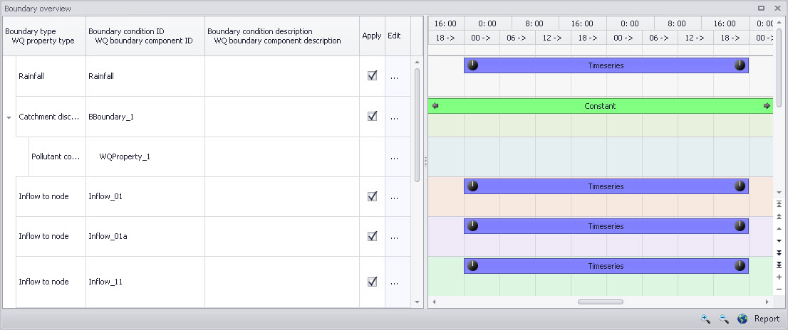
Figure: The Boundary Overview appears when pressing the ‘Boundary Info.’ button
'Set max. time' button
The 'Set max. time' button sets the maximum simulation time by filling in the start and end times of the simulation. The start time of a simulation is considered the latest start time of all boundaries. Likewise the end time for the simulation is considered the earliest end time of all boundaries.
Each boundary contains a number of items which can cover different parts of the simulation.
If a limited validity interval is specified for a boundary condition, this specifies the start and end time. If a validity is not specified, only items specified as timeseries have a start and end time. If either a constant or cyclic value is given without validity interval, the item is not included in the evaluation.
Catchments
The following parameters can be specified on the Catchments tab:
- Surface runoff model simulation time step
- RDI simulation time step
- Catchment discharge simulation time step
- Spatial distribution of rainfall
- RDI hotstart specification
- Additional parameters specification
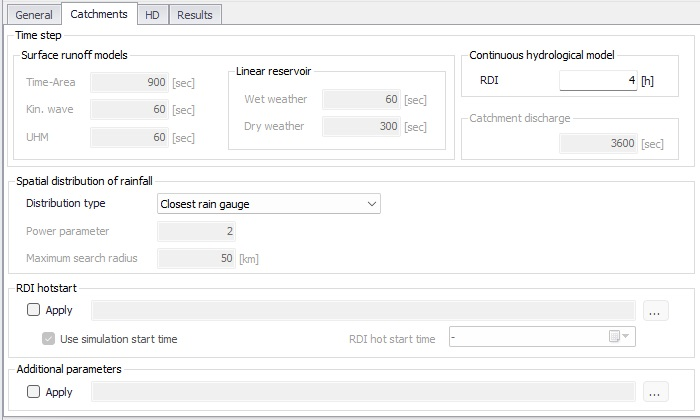
Figure: The Simulation Setup Catchments tab
| Edit field | Description | Used or required by simulations | Field name in datastructure |
|---|---|---|---|
| Time-Area | Fixed time step for Time-Area runoff model | Yes if at least one catchment is set for simulation with Time-Area model | TSDt |
| Kin. Wave | Fixed time step for Kinematic Wave runoff model | Yes if at least one catchment is set for simulation with Kinematic Wave model | KWDt |
| UHM | Time step for UHM model | Yes if at least one catchment is set for simulation with UHM runoff model | UHMDt |
| Wet weather | Time step during wet periods | Yes if at least one catchment is set for simulation with Linear Reservoir runoff model | DtWetPeriod |
| Dry weather | Time step during dry periods | Yes if at least one catchment is set for simulation with Linear Reservoir runoff model | DtDryPeriod |
| RDI | RDI slow runoff component time step. The fast runoff component time step is the corresponding surface runoff model time step. | Yes if at least one catchment is set for simulation with RDI runoff model | SRCDt |
| Catchment Discharge | Time step for catchment discharge | Yes if Catchment Discharge simulation active | CDDt |
| Distribution type | When rainfall boundary conditions are defined with the geographical location of the rain station (boundary type 'Data source location'), it is possible to control how the rainfall intensity from the various rain gauges (boundary conditions) are applied to the different catchments. Three methods are available: assign the closest rainfall time series to each catchment, apply weighting using Thiessen polygons, or apply weighting using an inverse distance interpolation. Weights can be reviewed in the 'Boundary conditions' editor. | Yes, if rainfall boundary conditions are of spatial extent type 'Data source location' | DistribTypeNo |
| Power parameter | The power coefficient, in the inverse distance interpolation equation. | Yes, when the distribution type is set to 'Inverse distance weighting'. | Power |
| Maximum search radius | The maximum distance for searching rainfall stations, in the inverse distance interpolation equation. | Yes, when the distribution type is set to 'Inverse distance weighting'. | SearchRadius |
| RDI Hotstart Apply checkbox | If this checkbox is ticked, a hotstart file for RDIImust be specified. | Optional | RDIHotStartNo |
| Use simulation start time | If 'Use simulation start time' option is enabled, the initial condition is automatically extracted from the hotstart file using the simulation start date and time as specified in the 'Simulation Setup' editor. | Optional | RDIHotStartTimeUseNo |
| RDI hotstart time | The date and time at which the initial conditions are loaded from the hotstart file. Only active if 'Use simulation start time' option is inactive. | Optional | RDIHotStartTime |
| Additional Parameters Apply checkbox | If this checkbox is ticked, an *.ADP file for the runoff simulation can be specified | Optional | ADPRunoffFileNo |
Table: The Simulation Setup Catchments tab attributes (Table msm_Project)
The additional parameter file (*.ADP file) is a separate file from MIKE URBAN with additional settings for the simulation, which is supported in MIKE+ for backward compatibility with MIKE URBAN.
HD
For a network (CS network and/or river network) simulation, the tab holds parameters specific to the hydrodynamic simulation setup:
- Fixed simulation time step, or
- Adaptive simulation time step settings
- Network initial condition type
- Additional parameters
For a simulation including 2D overland, the time step parameters are changed to:
- A fixed simulation time step, used by the network simulation. This time step is also used to determine the saving frequency of 2D overland result files, and to synchronize the HD and AD modules for the 2D overland simulation.
- Adaptive time step settings, applying only to the 2D overland simulation.
The tab is active if a hydrodynamic (HD) module is activated and if relevant data exist in the project (e.g. if at least 1 conduit is specified).
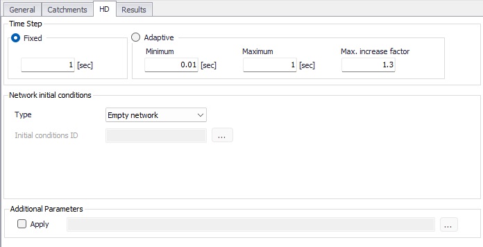
Figure: HD tab of the Simulation Setup editor
For network simulations, the initial condition definition may be of the following types:
- Empty network: with this option, the network will be empty at the first time step of the simulation, except at outlet nodes where water levels from possible boundary conditions will propagate into the network.
- User-specified: with this option, a set of initial conditions must be selected. Sets of initial conditions contain definition of default values, local values, and hotstart files. They are defined in the 'Initial conditions' editor.
- State file: with this option, initial conditions for all modules included in the simulation (Hydrodynamic, Rainfall-runoff, Transport, etc.) are obtained from a state file, which is a detailed result file from a previous simulation. It is therefore required that state files have been saved during a previous simulation (see Result files). For this type of initial condition, it is required to provide a path to the folder containing the state files created from the previous simulation, along with a date and time controlling which time step (i.e. which state file) will be used as initial condition. The appropriate state file from the selected folder, with the date and time the closest to the specified instant, will be selected automatically during the simulation. If 'Select state file using simulation start time' is ticked, the state file with the date and time the closest to the simulation start date will automatically be selected, otherwise the state file with the date and time the closest to the user-defined date and time will be used. A set of 'Initial conditions ID' must also be selected: initial conditions from the state file have the highest priority, but if the network has e.g. been extended and some calculation points do not exist in the state file, the initial conditions in these points will be controlled by the user-defined initial conditions.
- Steady state: with this option, initial conditions will be based on a steady state calculation for all rivers in the model, except for locations where local user-defined values are defined in the optional user-defined 'Initial conditions ID'. Default values and hotstart files defined in the selected 'Initial conditions ID' are ignored. This option is not supported for collection system networks.
| Edit field | Description | Used or required by simulations | Field name in datastructure |
|---|---|---|---|
| Fixed/Adaptive radio buttons | Toggles between alternative time step type | Yes | HDTimeStepType |
| Fixed | Specifies a fixed time step for the network simulation | Yes if Fixed time step type or if including 2D overland | HDDtFixed |
| Minimum | Specifies a minimum time step for network or 2D overland model | Yes if Adaptive time step type or if including 2D overland | HDDtMin |
| Maximum | Specifies a maximum time step for network or 2D overland model | Yes if Adaptive time step type or if including 2D overland | HDDtMax |
| Max. Increase Factor | Specifies maximum increase factor for adaptive time step for network model | Yes if Adaptive time step type | HDDtIncreaseFactor |
| Max. CFL number | Specifies the expected maximum CFL number in the simulation, to control the adaptive 2D overland time step | Yes if including 2D overland | M2DHDMaxCFL |
| Network initial conditions type | Specifies the type of initial condition for the network (CS and/or river) | Yes if including CS network or River network simulation | HDInitCondTypeNo |
| Initial conditions ID | Specifies the ID of the set of initial conditions, defined in the 'Initial conditions' page | Yes except if defined as ‘Empty network‘ | HDInitCondID |
| State files folder | The path to the folder containing the state files saved during a previous simulation | Yes if 'State file' is chosen | StateFilesFolder |
| Select state file using simulation start time | If selected, the simulation will use the state file with date and time matching the start time of the simulation. | Yes if 'State file' is chosen | UseSimulationTypeNo |
| Date and time | The user-defined date and time to select the state file from all state files saved during a previous simulation | Yes if 'Select state file using simulation start time' is not chosen | StateStartTime |
| Additional Parameters Apply checkbox | Activates .ADP file with network-relevant input. Define .ADP file name and path if activated. | Optional | ADPNetworkFileNo |
Table: The Simulation Setup HD tab attributes (Table msm_Project)
The additional parameter file (*.ADP file) is a separate file with additional settings for the simulation. Please refer to the seperate documentation on this file for further information.
AD and WQ
The "AD and WQ" tab includes parameters specific for the AD and MIKE ECO Lab (WQ) simulation setup.The tab is available if the Transport (AD, SWQ) module is activated in the ‘General’ tab, otherwise it is hidden.
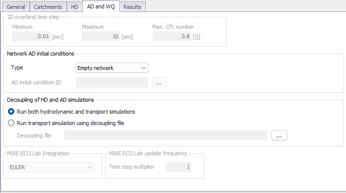
Figure: The Simulation Setup AD and WQ tab
| Edit field | Description | Used or required by simulations | Field name in datastructure |
|---|---|---|---|
| Minimum | Specifies a minimum time step for 2D overland model | Yes if including 2D overland | M2DADDtMin |
| Maximum | Specifies a maximum time step for 2D overland model | Yes if including 2D overland | M2DADDtMax |
| Max. CFL number | Specifies the expected maximum CFL number in the AD simulation, to control the adaptive 2D overland AD time step | Yes if including 2D overland | M2DADMaxCFL |
| Type | Controls whether the simulation start with an empty network (no component) or with pre-defined initial conditions | Yes | ADInitContTypeNo |
| AD initial condition ID | The ID of the selected set of Network AD initial conditions | Yes if Type = User-specified | ADInitCondID |
| Decoupling of HD and AD simulations | Decoupling a transport simulation (AD or WQ) from the HD simulation speeds up the simulation by getting the hydrodynamic conditions from a decoupled result file, instead of running the HD simulation at the same time. This is especially relevant when running multiple transport simulations with identical HD conditions. | Yes | DecouplingADHDTypeNo |
| Decoupling file | The decoupled result file to be used as input for the decoupled transport simulation. It is a result file with content type 'Decoupling' which must be saved during a previous simulation. | Yes, if 'Run transport simulation using decoupling file' is chosen | DecouplingPath |
| MIKE ECO Lab Integration | Specified ECOLab integration method | Yes If Simulation Type = MIKE ECO Lab (WQ) | ELIntegrationNo |
| Time step multiplier | Multiplier used to scale the MIKE ECO Lab time step as a function of the HD time step | Yes | ELUpdateFrequency |
Table: The Simulation Setup AD and WQ tab attributes (Table msm_Project)
LTS
The LTS tab includes parameters specific for Network LTS simulations. The tab is shown if the Long Term Statistics (LTS) module is activated in the project and if at least 1 Job List Criterion is specified.
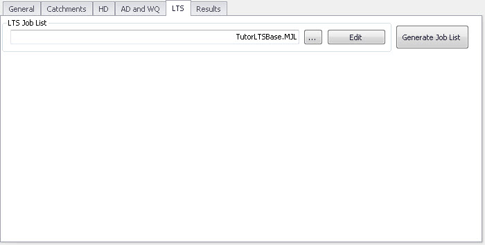
Figure: The Simulation Setup editor LTS tab
| Edit field | Description | Used or required by simulations | Field name in datastructure |
|---|---|---|---|
| LTS Job List | Defines the Job List *.MJL file name and path to be used in the LTS simulation | Yes If Simulation Type = Long Term Simulation (LTS) | MJLFileName |
Table: Simulation Setup LTS tab attributes (Table msm_Project)
The LTS tab also has buttons for the following functions.
'Edit' button
Opens the specified Job List file (*.mjl) in text editor. If the Job List File dialog is empty, or the specified file does not exist or is empty, the ‘Edit’ button opens an empty ASCII file.
'Generate Job List' button
Starts a Job List generation process. This is a special form of simulation where the output is a Job List file (*.MJL).
More details on Job List generation and editing are found in section Data Input and in the MIKE 1D Reference Manual.
Results
The Results tab includes parameters for defining output from a simulation setup.
Multiple result files may be specified for each simulation setup.
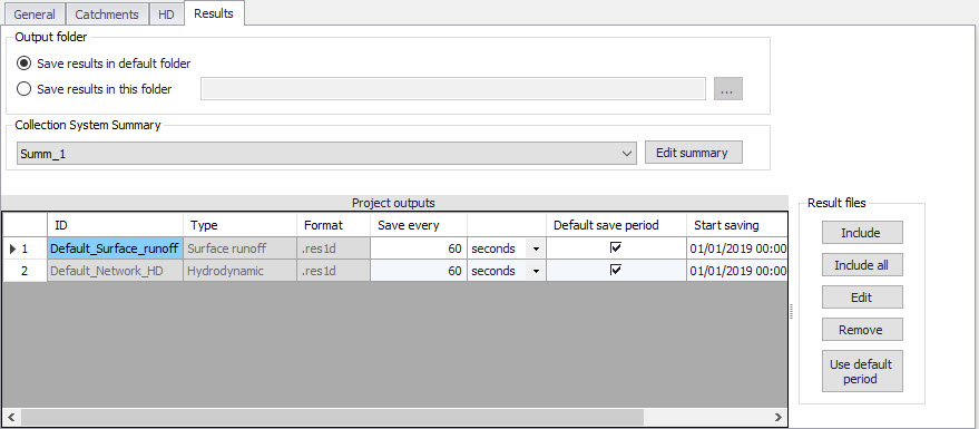
Figure: Results Tab of the Simulation Setup editor showing multiple result items
| Edit field | Description | Used or required by simulations | Field name in datastructure |
|---|---|---|---|
| Save Results in Default Folder/Save Results in this Folder [Output Folder radio buttons] | Toggles between Default folder and user-specified folder for output file location | Yes | HDOutputNo |
| [Input box beside ‘Save Results in this Folder ‘option] | Contains the path for user-specified output destination folder | Yes if ‘Save Results in this Folder’ activated | HDFolderPath |
| Collection System Summary dropdown menu | Specifies a MIKE1D simulation summary. User selects from the list of available summaries. Only one network summary per simulation job is possible. | Yes if including a network simulation | SummaryID |
| Edit Summary button | Opens the Network Summary editor with the current summary in focus. Allows for editing summary contents. If user has specified a non-existing summary ID, program automatically creates a new summary record with default contents and opens the summary editor with the new summary in focus. | Yes | - |
Table: Overview of Simulation Setup Results tab attributes (Table msm_Project)
A secondary grid in the 'Results' tab displays a list of the output files selected for the simulation setup. The grid retrieves the information from the Result Files editor (Result Specifications| Result Files).
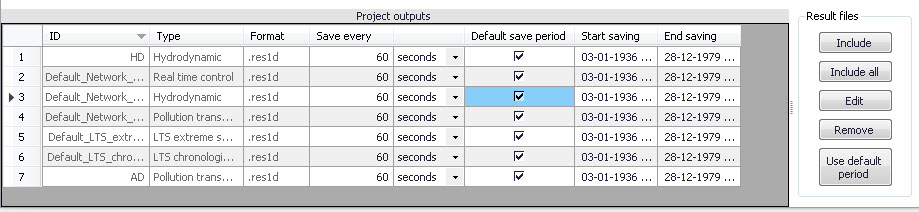
Figure: The Project Outputs secondary grid in the Results tab
An overview of the attributes of the 'Project Outputs' table is shown in the table below.
| Edit field | Description | Used or required by simulations | Field name in datastructure |
|---|---|---|---|
| ID | MUID of the selected output file definition | Yes | OutputID |
| Type | Shows type and default contents of the output file (read only) | Yes | ContentsTypeNo |
| Format | Shows the file format (read only) | Yes | FormatNo |
| Save Every | Specifies results saving frequency | Yes | DtSave |
| [Column to the right of ‘Save Every’ column] | Specified unit for result saving frequency | Yes | DtSaveUnitNo |
| Default Save Period checkbox | Specify to save results for the entire simulation (check), or for user-specified period only (un-check) | Yes | DefaultSavePeriodNo |
| Start Saving | Defines start date and time for saving results | Yes if user-specified save period | SaveStartDate |
| End Saving | Defines end date and time for saving results | if user-specified save period | SaveEndDate |
Table: Overview of the Project Outputs secondary grid attributes (Table msm_ProjectOutput)
The list of outputs is controlled by the user using available buttons to the right of the grid. The following buttons are available.
'Include' button
Opens a list of all relevant results definitions as specified in the 'Result files' editor and allows to choose those which are to be added to the list. The list is filtered to show only the relevant results according to the features and modules included in the actual simulation.
'Include all' button
Fills the list with all relevant results defined in the 'Result files' editor. Relevance is determined by the modules and features included in the simulation. If the list is not empty, it only adds those outputs which are not already in the list.
'Edit' button
Opens the 'Result files' editor with the current result in focus.
'Remove' button
Removes selected result(s) from the list.
'Use default period' button
This function resets the 'Start saving' and 'End saving' date and times for each result file, to match the start and end date of the simulation.