Air-Chambers
Air-chamber nodes are placed at points in the water distribution model where an air-chamber tank is located. Please note that air-chambers are used in surge protection and that they are part of the water hammer module in Special analyses. They have no hydraulic function during the EPANET-based simulations and they are treated as dead-end nodes. Air-chambers are described by their volume and the initial water level that defines the ratio between the water and pressurized air. Air-chamber nodes are either defined interactively on the graphical Map window using the Add Air-chamber tool, or by manual data entry using the Air-chambers editor.

Figure: The Air-chambers editing tools
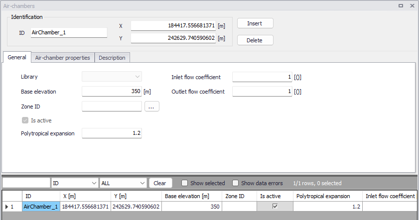
Figure: The Air-chambers editor
The Air-chambers editor contains input fields for geometry, air-chamber's properties, and description.
A list of the Air-chambers editor attributes follows, with a short description given for each one.
Identification
ID (mandatory)
This is used to specify an ID which uniquely identifies the air-chamber node. The air-chamber ID acts as a unique lookup key that identifies the node from all other nodes. A node can be a junction, reservoir, tank, or air-chamber. Therefore, two nodes cannot have the same ID. The ID can be any text up to 40 characters.
X and Y coordinates
The X and Y data entries are used to define the physical (map) location of the Air-chamber node. Their unit is controlled by the unit system used in the project.
General
This tab gives general information of air-chambers as shown in figure below.
Figure: The General tab of the Air-chambers editor
Base elevation (mandatory)
Base elevation defines the distance from bottom of the air-chamber above datum elevation.
Zone ID (optional)
This is an optional name for the zone to which the air-chamber belongs. When a zone ID is specified, this zone will be listed in the 'Zones' editor. The '…' button can be used to select an existing zone.
Is active
This check box controls whether the air-chamber will be included (when ticked) or omitted (when unticked) in the simulations. The air-chamber is automatically omitted as soon as all connected links are also set to inactive.
Polytropic expansion (mandatory)
Polytropic expansion is the exponent in the polytropic gas equation (value 1.0 for an isothermal expansion, value 1.4 for adiabatic expansion) with the default value of 1.2.
Inlet flow coefficient
It represents the flow coefficient t applied to the inlet pipe when the water flows into the air-chamber.
Outlet flow coefficient
It represents the flow coefficient t applied to the inlet pipe when the water flows from the air-chamber.
These two flow coefficients are used in the head loss calculation as follows.
Headloss, dH:
(3.2) 
where v is the flow velocity and \(\xi\) is the minor loss coefficient
(3.3) 
Air-chamber properties
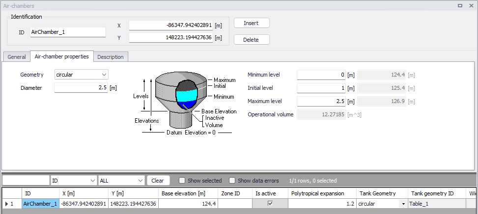
Figure: The Air-chamber properties tab
Geometry (mandatory)
This drop-down selection list selects the type of air-chamber being defined:
- Table
- Rectangular
- Circular.
For different types of air-chambers, the required geometry data is different. By default, a circular air-chamber is defined. The 'Table' option is used for air-chambers whose cross-sectional area varies with height.
Diameter (mandatory)
The diameter of the air-chamber, when the geometry type is set to circular.
Length and width (mandatory)
The size of the air-chamber, when the geometry type is set to rectangular.
Geometry ID (mandatory)
When the geometry type is set to 'Table', the geometry ID holds the ID of a table containing the elevation-volume relationship. This table has to be defined in the 'Curves and relations' editor, with table type 'Tank depth-volume'. This relationship determines how the air-chamber's volume varies as a function of water level. The lower and upper water levels supplied in the table must contain the lower and upper levels between which the air-chamber operates.
Minimum level (mandatory)
This defines the minimum level (or depth), that the water can drop to within the air-chamber. The corresponding elevation is equal to the base elevation plus the minimum level.
Initial level (mandatory)
This defines the initial water surface level (or depth), that is used at the start of the simulation. The corresponding elevation is equal to the base elevation plus the initial level.
Maximum level (mandatory)
This defines the maximum level (or depth), that the water can rise to within the air-chamber. The corresponding elevation is equal to the base elevation plus the maximum level.
Operational volume
This volume is derived from the above geometrical properties of the air-chamber, and represents the usable volume, which can be filled or released from the tank.
For circular and rectangular air-chambers, the volume equals the horizontal area of the air-chamber times the difference between its maximum and minimum water levels.
For air-chambers defined using a geometry table, the operational volume is the difference between the volume of the table at the maximum level, and the volume of the table at the minimum level. Volumes at the maximum and minimum levels are obtained using a linear interpolation from the table's data.
Description
Description (optional)
This allows providing a description of the air-chamber node. This description can be optionally displayed on the Map window and in reports generated by the Report tool.
Data source (optional)
This is used to specify a corresponding asset data source, which uniquely identifies the air-chamber location (such as database table or a database file name) in the asset management system.
Asset ID (optional)
This is used to specify a corresponding asset air-chamber ID, which uniquely identifies the air-chamber node in the asset management system (such as GIS, for example).
Status (optional)
This drop-down selection list allows you to define whether the air-chamber node is imported (i.e existing node was imported from the external data source), or is inserted, modified, GIS, calibrated or similar.
Add picture
The 'Add picture' button allows to add a photo of the air-chamber. Once loaded from external source, the picture will be displayed on the right section of the editor.
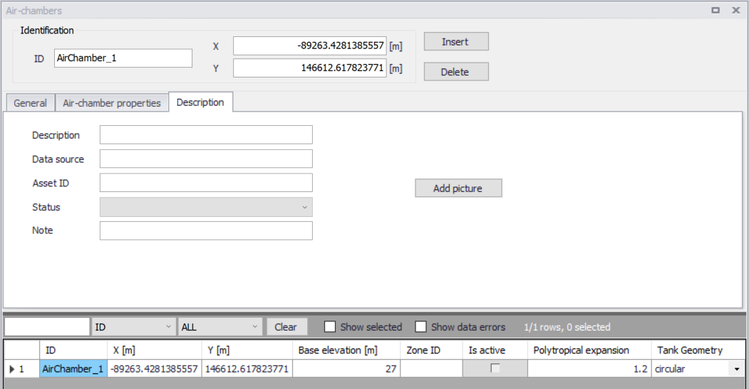
Figure: The Description tab of the Air-chambers editor
Note
Air-chambers are used in water hammer analyses. Refer to chapter Water Hammer for more information.