Discharge Through Section Tool
Introduction
The purpose of the 'Discharge through section' tool is to calculate the discharge on the surface through cross sections (i.e. polylines on the map), from both 1D and 2D result files.
If both 1D and 2D results are included, the tool provides one .dfs0 file for each section (polyline), each file containing the discharge time series from the 1D result file, the time series from the 2D result file, and the sum of the two. When a section only covers one of the two types of result file, or when only one type of result file is selected in the analysis, then the created .dfs0 file contains only one time series obtained either from the 1D or the 2D result file.
The tool is opened from the 'Results' tab in the ribbon.
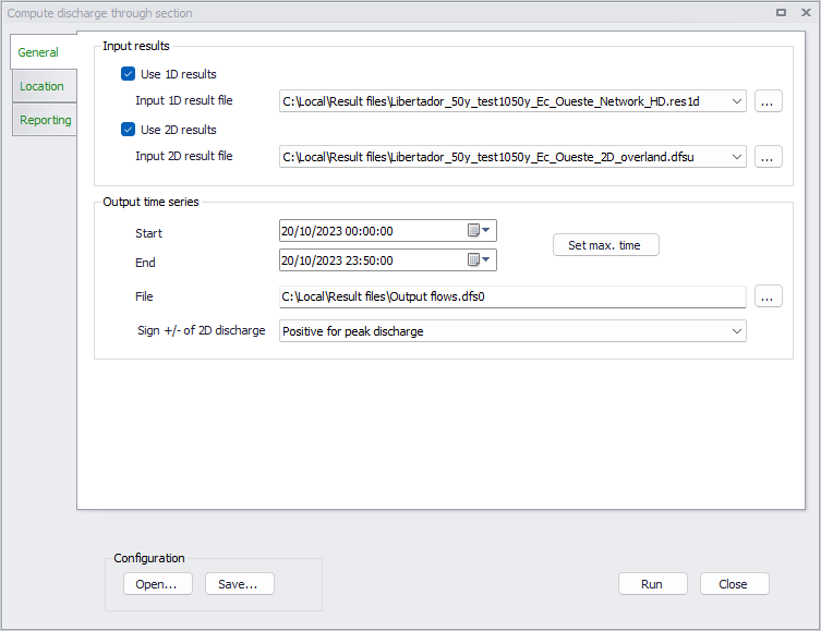
Figure: The Discharge through section tool
Time series values obtained from the 1D network are the exact discharge values obtained from the closest (to the section drawn on the map) calculation point on the network. Time series values obtained from the 2D results are computed from results in the various elements on the mesh along the polyline.
When processing only a 1D or only a 2D result file, the output time series gets the same time step as the input result file. When processing both 1D and 2D result files, values from the result file with the coarser time step are interpolated, so that the output time series gets the same time step as in the result file with the smaller time step.
The tool is primarily designed to estimate discharge on the surface and therefore to work with open channels for 1D results. It will anyway also work with closed pipes and get discharge results from these pipes, if the polylines cross any of them.
General settings
The 'General' tab holds selections of input result files to be processed, as well as output settings.
Use 1D results
Activate this option if the computed discharge time series should include discharge results simulated in a 1D model network. When active, a 1D result file must be selected either from the list of result files loaded in the MIKE+ project, or by selecting another file with the '…' button. Only 1D result files from MIKE 1D simulations (.res1d files) and from network simulations are supported.
If this option is unselected, the tool can be used to get discharge time series from 2D results only.
Use 2D results
Activate this option if the computed discharge time series should include discharge results simulated in a 2D overland model. When active, a 2D result file must be selected either from the list of result files loaded in the MIKE+ project, or by selecting another file with the '…' button.
The selected result file must contain at least one of the following combinations of result items:
- P flux, Q flux
- Total water depth, U velocity, V velocity
- Surface elevation, Still water depth, U velocity, V velocity
- Surface elevation, U velocity, V velocity.
Output start and end time
'Start' and 'End' date-times define the time period which will be saved in the output time series files. This period must match or be within the common period covered by the input result files.
The 'Set max time' button can be used to define the period so that it matches the common period of the input result files.
Output file
The specified output file name and location are used as base name for naming output time series. The actual output file names are based on this specified name, with the individual section names as suffix.
Sign +/- of 2D discharge
This option is only relevant for time series obtained only from 2D results. It has two options:
- Depends on direction of the section's digitization: with this option, the sign of the discharge values depends on the direction in which the section's polyline has been digitized. When looking in the direction of the digitization of the polyline, the discharge is considered positive when water flows from the left to the right, and negative when it flows from the right to the left.
- Positive for peak discharge: with this option, the output time series is corrected so that the maximum absolute value is always positive. When the maximum absolute value is found to be negative, the sign of all time step values is inverted. That means that the resulting corrected time series may still contain negative values at time steps where the water is flowing in the opposite direction than the direction found for the maximum value.
When the time series include 1D results, the direction is always based on the river direction, i.e. the discharge is assumed positive when water flows from upstream to downstream.
Notes on the discharge calculation
The following has to be noted:
- Flux on open boundaries will not be included.
- It is not possible to get correct calculations for partially wet elements since the result file has insufficient information for this. Flux on faces with neighbor cell that has delete values will be set to zero.
- The flux on a face in the input result file is an approximation to the 'real' flux used in the engine that produced the result file.
Location
This tab holds sections (i.e. polylines) through which the discharge is to be computed.
Sections are defined in the left table, with a name which is added as a suffix to the output file name. New sections can be added using the 'Add on map' button, to digitize them on a map, and can be removed using the 'Delete' button. Sections are processed only if their 'Include' check box in this table is selected, whereas unselected sections are ignored.
The table on the right gives coordinates of all vertices from the section selected in the left table. A polyline can therefore be edited from the table, by editing X and Y coordinate values, adding more vertices using the 'Insert' button or deleting vertices using the 'Delete' button. The 'Edit on map' button alternatively switches the polyline in edit mode on the map, after what it is possible to move vertices on the map, add new vertices by clicking on the line, or delete vertices by double-clicking. Right-click on the map to end editing the polyline.
When processing 2D results, the polyline must be within the extent of the 2D results. When processing 1D results, it cannot cross the same 1D channel more than once. Crossing different 1D channels is supported but in that case the line must cross all channels in the same direction (e.g. from the left bank to the right bank).
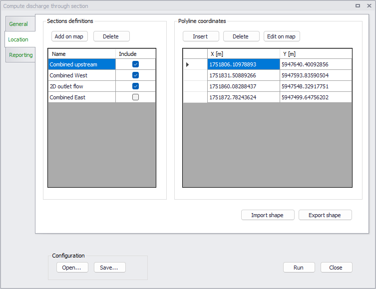
Figure: The definition of sections in the Discharge through section tool
Sections may be imported from a shape file using the 'Import shape' button. This action will add sections from the shape file to those already existing in the table. Sections defined in the tool can also be exported to a shape file using the 'Export shape' button.
Reporting
Once a discharge calculation is run, status and errors are reported in this tab of the tool. This report can be saved for further inspection at a later stage.
Configuration
Once the tool has been configured, it is possible to save its configuration to a file using the 'Save…' button for later re-use. This configuration can later be loaded again using the 'Open…' button, or can be used to execute the tool from a command line.
Running the tool from command lines
MIKE+ user interface is usually the preferred way to execute this tool. However, there are times when it may be more convenient to execute the tool in an automated way without opening it in the user interface.
The MIKE+ executables enable you to execute some tools without opening their editor, through command lines. It is possible to run the 'Discharge through section' tool in this manner, assuming you have prepared the configuration file beforehand in MIKE+.
Start by locating the MIKE+ executable named DHI.MIKEPlus.ToolShell.exe in the installation folder. From a command prompt, type the command below to access the list of supported tools, replacing the … characters by the actual path to the file::
The format of the command for running the 'Discharge through section' tool is:
Where [Configuration file] is the path to the *.xml configuration file.