1D-2D Couplings Editor
Integrated modelling requires couplings between stormwater pipes, open channels, streams, rivers, and the overland surface. Such couplings between network and overland models are defined in the '1D-2D couplings' editor.
The following coupling types are available, and are used as appropriate for different 1D model components:
- Manhole
- Basin
- Outlet
- Soakaway
- Pump
- Weir
- Natural channel
- Junction (SWMM5)
- Storage unit (SWMM5)
- Flow divider (SWMM5)
- Outfall (SWMM5)
- River bank
- River end
Note
Couplings between SWMM5 and 2D overland models can ony be defined at node elements (e.g. junctions, outfalls). Coupling along open SWMM5 conduits' banks are not supported.
The following sections describe how to manually define individual couplings in the '1D-2D Couplings' editor. Alternatively, couplings may be batch-generated using Coupling tools.
In the '1D-2D couplings' editor, new couplings are inserted using the 'Insert' button. The following attributes then need to be specified for each coupling.
Identification
Each coupling definition has a unique ID (editable) and information on the 1D network item type coupled (e.g. manhole, basin, river bank, pump, etc.).
There is also a switch to control which couplings are activate during a simulation via the ’Apply’ tick box.
When coupling to an external MIKE HYDRO River model setup, some coupling types can be coupled to either the 2D overland model or to a 1D network model. A 'Couple to' option allows whether the item is to be coupled to the collection system network, to the MIKE HYDRO River network, or to the 2D overland model.
Location
Specify the location of the 1D and 2D components to be coupled.
Couplings to Nodes and Structures
ID
The node or structure ID to be coupled that can be selected from a drop-down list that corresponds to the selected ’Type’.
Warning
For coupling types using the ’Inlet area’ parameter in the ’Attributes’ tab, the area is recomputed to a default value whenever the node ID is re-selected from the list. The default value is based on node geometry. For SWMM5 models where nodes have no diameters, the Inlet Area parameter is initially assigned a value of 0.
Location in 2D Domain
When coupling a node or structure to the 2D overland model, the location of the coupling is defined in the 'Location in 2D domain' secondary table. The default location is a point corresponding to the location of the coupled item. For a weir or pump, it corresponds to the location of its 'From node'. During the simulation, an item coupled to a single point location will be coupled to the 2D cell in which it lies.
The coupling may instead be defined with a polygon, in which case the 'Location in 2D domain' secondary table must contain at least three points /locations. In this case, more than one 2D cell is coupled to each 1D item, and the flow will be distributed amongst the cells when flowing from the 1D item. This feature is useful if you expect high flows that could cause computational instabilities. Points defining the polygon can be added, removed, or reordered using the buttons next to the table. In general, using multiple cells or an area as opposed to coupling to only one point will enhance computational stability.
The 'Square width' option automatically updates the coupling to a polygon with a square shape and with the specified width when the ’Update’ button is clicked.
Warning
The location is reset to a default location every time the coupled item is changed.
If a node/pump/weir link couples to multiple cells in the 2D overland model, the ground level in the 2D overland model is taken as the average level from coupled cells/elements. In each cell/element, the coupling acts as a simple source where only the mass is taken into consideration (no momentum).
Location on Coupled River
If the collection system network is coupled to both the 2D overland model and to MIKE HYDRO River, coupling an outlet, a pump, or a weir requires specifying whether the selected item is coupled to the 2D model or to MIKE HYDRO.
If coupled to the 2D overland model, the description from the previous chapter applies. If coupling to MIKE HYDRO, the coupling location is only defined by a chainage along a river, and no other attributes are required.
Couplings to Natural Channel, River Bank, MIKE HYDRO River Bank
The coupling types ’Natural Channel’, ’River bank’ and ’MIKE HYDRO River bank’ all describe lateral coupling of a channel that describes overbank spilling towards the floodplain in the 2D overland model or drainage of the floodplain by the river. The parameters required for these three coupling types are identical: only the source of the channel information differs.
Note
At present, there are no options for laterally coupling SWMM5 open conduit banks to 2D overland models.
ID
This is the ID of the natural channel or river to be coupled that can be selected from a list.
For the coupling type ’Natural Channel’ only the channels defined in Network | Pipes and Canals, where Link type = Natural Channel, will be available in the list.
From Upstream/To Downstream Chainage
Specify the section of the channel, from the upstream to the downstream chainages, that is to be coupled to 2D.
Side
Define on which side of the channel over the flow will spill in/out between the 1D and 2D domain.
Note
If both sides of the channel need to be coupled, two couplings need to be specified.
The choice of the side controls the location of the created coupling line in the 2D domain, and therefore controls which cells/elements will be coupled to the 2D domain. The location of the coupling line is based on the markers specified in the cross sections of the channel, where marker 1 is the left bank and marker 3 is the right bank.
Location in 2D domain
There are usually many cells/elements in the 2D overland domain which are linked to the channel. These cells/elements are selected using the coupling line shown on the map, which coordinates are shown in the 'Location in 2D domain' table in the editor. During the simulation, the channel will be coupled to faces of cells/elements nearest to the coupling line.
This line and its table of coordinates are automatically populated with a default location when the channel ID, chainages, and coupled sides are specified. It is however possible to manually adjust its location, either graphically on the map or from the table, to refine the selection of coupled faces. The table also includes a 'Chainage' column controlling the chainage of the channel being coupled to the nearest cells/elements faces.
The following methods are available for controlling the 2D element faces to be coupled:
- Insert/Delete: Manually insert, edit, and delete the vertices of the coupling line controlling which 2D cells/elements will be coupled.
- Up/Down: Control the order of the vertices. The coupling line must stretch continuously from upstream to downstream.
- Insert from file: Import the x- and y-coordinates from an external file (*.XYZ or *.SHP files)
- Coupling Tools menu ribbon: The Edit tool in the ribbon can be used to edit the coupling line graphically on the Map.
If multiple couplings have to be created, the process can be automated using the Create Couplings tool.
Tip
If cross sections of channels in a model setup are generally wider than the width of the cells/elements in the 2D domain, it may be appropriate to exclude the cells in the 2D domain lying within the channel bed and hence avoid flow calculation by the 2D model in these cells. Thereby, it can be ensured that the water body within the main river is not included twice in the coupled model simulations. Use the Exclude Rivers tool available via the 2D Overland menu ribbon to exclude the river extent from the 2D computational mesh/grid.
Couplings to River End, MIKE HYDRO River End
River ID
The river's name (specified in River network | Rivers or in MIKE HYDRO River) to be coupled that can be selected from a list.
River End
The selection between the upstream or downstream end of the river, which is being coupled.
Location in 2D domain
When the end of a river is coupled to the 2D overland model, the river end is coupled to a string of element faces from the 2D domain. The coupled element faces are the closest faces from the coupling line, defined in the 'Location in 2D domain' secondary table.
The table is automatically populated with the default location corresponding to the end cross section on the river when the channel ID and Upstream/Downstream ends are specified.
The following methods are also available for controlling the 2D element faces to be coupled:
- Insert/Delete: Manually insert, edit, and delete the vertices of the coupling line controlling which 2D cells/elements will be coupled.
- Up/Down: Control the order of the vertices. The coupling line must stretch continuously from one side of the river to the other.
- Coupling Tools menu ribbon: The Edit tool in the ribbon can be used to edit the coupling line graphically on the Map.
If multiple couplings have to be created, the process can be automated using the Create Couplings tool.
Node ID
When the end of a river from a MIKE HYDRO River model setup is coupled to a node from the collection system network, the node ID must be defined. The node can be selected from the ellipsis button '...', or using the ’Get closest’ function, which will find the node on the collection system network closest to the river end.
Couplings to Side Structure
River ID
The river branch's name from the coupled MIKE HYDRO River model setup where the coupled structure is located.
Structure ID
The ID of the structure being coupled. Note that only structures of ’Side structure’ type along the selected river will show up in the list.
Side
The choice between left and right sides controls along which side of the river the structure will be coupled in the 2D domain.
Length and Distance from River
This value is used to control the default location of the coupling line, provided in the ’Location in 2D domain’ secondary table, as described below. The value is not used in the simulation, i.e. if the table is manually adjusted, only the coordinates from the table are considered for the simulation whereas the ’Length and distance from the river’ value will be ignored.
Location in 2D domain
When a side structure from a MIKE HYDRO River model setup is coupled to the 2D overland model, the structure is coupled to a string of element faces from the 2D domain. The coupled element faces are the closest faces from the coupling line defined in the 'Location in 2D domain' secondary table.
The table is automatically populated with a default location when the structure ID and ’Length and distance from the river’ values are specified. The default location is a straight line parallel to the river with a length equal to ’Length and distance from the river’ value, and placed at a distance from the river also equal to ’Length and distance from the river’ value.
The following methods are also available for controlling and editing the 2D element faces to be coupled:
- Insert/Delete: Manually insert, edit, and delete the vertices of the coupling line controlling which 2D cells/elements will be coupled.
- Up/Down: Control the order of the vertices.
- Coupling Tools menu ribbon: The Edit tool in the ribbon can be used to edit the coupling line graphically on the Map.
Attributes
Define how water is transferred between the 1D and 2D models through the coupling definitions and flow exchange parameters in the Attributes tab page of the 1D-2D Couplings editor.
Couplings to Nodes
The coupling to nodes is designed to describe the interaction of water when a manhole, basin, junction, storage unit, slow divider, or soakaway node is overtopped, or when overland flow enters and exits a sewer/storm water network.
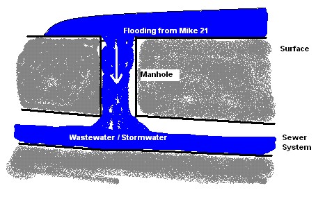
Figure: Flooding from overland into a non-surcharged sewer system
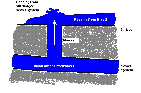
Figure: Flooding from a surcharged sewer system onto the 2D overland surface
The coupling to nodes may also be used for linking a sewer outlet/outfall node with the 2D overland topography. For example, to describe the dynamic interaction between a sewer system and a collection basin described using the 2D topography as opposed to describing the basin in the 1D model.
Smoothing Factor
This parameter introduces an exponential smoothing of the water level values transferred from the 1D to 2D model. A value of 0 indicates no smoothing whereas a value closer to 1 creates stronger smoothing in the model. Values are only valid in the range [0 to 1].
- For couplings to manholes, basins, junctions, storage units, flow dividers, and soakaways in the sewer model, the smoothing is applied to the node water level and the 2D water level used for calculating the interacting discharge.
- For outlets/outfalls in the sewer model, the smoothing is applied to the 2D water level transferred to the collection system network.
The higher the value, the greater the smoothing will be. The parameter impacts the dynamics by smoothing out steep gradients (in time) through the couplings. In general, the exponential smoothing factor should be adjusted when a structure exhibits unstable behaviour (e.g oscillates wildly).
A high smoothing factor will cause a time lag in the transfer of the values from one model component to the other.
Delta Depth for Dampening
This parameter indicates the water level difference from which the calculated discharge should be progressively suppressed. The delta depth may be used to stabilize setups where instability is caused by a small differences in the water levels in the coupled models.
If a value of 0 is given then no suppression is applied. When a positive value is given, the discharge is multiplied by a specified suppression factor between 0 and 1. When the water level difference between the node and 2D overland cell/s is greater than the delta depth, then the factor is 1. For water level differences dh less than the delta depth, the suppression factor is:
(5.1) 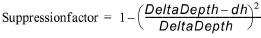
Max. Q
The coupling gives the option of placing an upper limit on the flow exchange. This is only available for couplings to manholes, basins, junctions, storage units, flow dividers, and soakaways. Care must be taken with this option. A simulation indicating that the max. value is in effect constantly may be hiding an oscillating flows being overridden by a fixed value.
When a time series boundary condition is applied as a network load to a collection system node that is also coupled to the 2D domain, it is fully applied to the network (not to the coupling) as network load, i.e. all of the discharge enters the network first and only then spills onto 2D domain.
However, when a rainfall runoff catchment load is applied to a node that is also coupled to the 2D domain, the runoff discharge is applied to the coupling, which results in the discharge to the network being restricted by the max. Q parameter. The remaining discharge is applied to the 2D domain.
Flow Description
The exchange of water at the coupling can be computed in four different ways:
- Orifice equation: The flow between 1D and 2D is governed by a standard orifice equation.
- Discharge coefficient: A non-dimensional factor that may be used to scale the orifice flow. By default the parameter should be close to 1.
- Inlet area: Describes the flow exchange between the urban and the 2D grid/mesh. The greater the cross sectional area the greater the conveyance capacity of the coupling. This parameter corresponds physically to the area of the manhole cover or stormwater inlet. The default inlet area is recomputed based on the manhole's diameter, or set equal to the last (highest) As value from the geometry table for a basin, when the node ID is selected. For SWMM5 models where nodes have no diameters, the Inlet Area parameter is initially assigned a value of 0. The max. Q value must be considered in conjunction with this parameter.
- Weir equation: The flow between 1D and 2D is described through a weir equation.
- Discharge coefficient: A non-dimensional factor that may be used to scale the weir flow. By default the parameter should be close to 1.
- Crest width: Describes the flow exchange between the urban and the 2D grid/mesh based on the weir formula. This parameter may correspond physically to the circumference of the manhole cover.
- Exponential function: The flow is governed by a simple exponential function. An increase in the exponent factor has a strong impact on the discharge. An increase in this value will generate a larger flow for a certain water level difference in the urban and the 2D model.
- Curb inlet function: This function is used when the flow between 1D and 2D represents flow transferred at a grate or inlet from a surface overland flow network to the sub-surface pipe network. The transfer capacity of the connection is specified as a DQ-relation (tabular data type). When water is transferred to the surface from the sewer pipe network the flow is calculated with the orifice equation.
- Discharge coefficient: As per the orifice flow description
- Inlet area: As per the orifice flow description
- Freeboard: Defines a critical water level (Ground level - Freeboard) at the connection node in the pipe network below which the defined DQ relation applies. For submerged and reverse flow (surcharge), the transfer capacity of the connection reverts to a standard orifice relationship.
- DQ relation ID: Click on the ellipsis button '...' to select from predefined DQ relationships specified in Tables | Curves and Relations. The DQ relation specifies the depth-based capacity curve for the curb inlet. Values must be monotonically increasing in depth and discharge starting at (0,0). For depths in excess of the maximum value specified in the last row of the table, the last corresponding discharge is used. Positive discharge is considered to flow from 2D into 1D (overland to sewer network).
Couplings to Pumps and Weirs
The coupling to the 2D overland model is also applicable to situations where the sewer system is discharging into the surrounding area through a pump or over a weir. In these cases the pump or the weir must be defined as having no downstream node in the 1D network.
Smoothing Factor
This parameter introduces an exponential smoothing of the water level values transferred from one model to the other model. A value of 0 indicates no smoothing whereas a value closer to 1 creates stronger smoothing in the model. Values are only valid in the range [0 to 1].
Couplings to Natural Channel, River Bank, MIKE HYDRO River Bank
The transfer of flow between a string of 2D cells/elements laterally linked to a given reach in the channel is described by the following attributes:
Smoothing Factor
This parameter introduces an exponential smoothing of the water level values transferred from 1D to 2D. A value of 0 indicates no smoothing whereas a value closer to 1 creates stronger smoothing in the model. Values are only valid in the range [0 to 1].
The greater the value, the greater the smoothing will be. The parameter impacts the dynamics by smoothing out steep gradients (in time) through the couplings. In general, the exponential smoothing factor should be adjusted when there is unstable behaviour in the coupled flow (i.e. oscillates wildly).
A high smoothing factor will cause a time lag in the transfer of the values from one model component to the other.
Delta Depth for Dampening
This parameter indicates the water level difference from which the discharge gradients should be progressively suppressed. The delta depth may be used for stabilizing setups where the instability is caused by a small difference in the water level in the two coupled models.
If a value of 0 is given then no suppression is applied and the model may experience numerical instability. The suppression varies with the water level difference and is only active when the water level difference is less than the depth tolerance.
Weir Description
Defines parameters for the weir flow calculation to be performed between the 1D and 2D components:
- Weir type: Either the Villemonte or Honma formula is used to describe the transfer of flow between the 1D channel and the 2D mesh/grid.
- Weir coefficient: Required for the weir formulas
- Crest source: Determines where the crest level geometry information comes from that is used for the lateral coupling, i.e. where the levee height should be extracted:
- Highest: Takes the maximum of the 2D topography and the 1D channel’s cross section markers (marker 1 for left coupling side and 3 for right coupling side).
- 2D Topography: The levee height is defined by the topography in the 2D topography. For stability reasons, the drying depth is added to the topography values when defining the levee height.
- Table: A table of values can be created or edited that defines the crest level profile. Chainages along the channel and crest levels are specified. This table is saved in Tables | Curves and Relations.
- External file: Information on link elevations as a function of distance along the coupling is introduced through an external *.DFS1 file. This file can be time varying and hence, can be used to simulate e.g. embankment levee changes and breaches during a simulation. Time-varying *.DFS1 files must be defined with a relative time axis (relative to the start time of the simulation). Browse to an existing file, edit the profile in a profile editor, or create a new profile using the ellipsis button '...'.
Note
The crest level should not be below the 2D topography nor below the bed level in the channel. Thus, if the selection is such that this occurs, MIKE+ will use the limiting value.
Couplings to River End, MIKE HYDRO River End, Side Structure
When coupling the end of a river or a side structure from MIKE HYDRO to the 2D overland model, the following attributes must be specified:
Smoothing Factor
This parameter introduces an exponential smoothing of the water level values transferred from one model to the other model. A value of 0 indicates no smoothing whereas a value closer to 1 creates stronger smoothing in the model. Values are only valid in the range [0 to 1].
Flow Distribution
A non-uniform distribution indicates that flow from the river is distributed into the coupled cells/elements according to their respective water depths. This is considered appropriate for couplings to natural terrain or channels, but may not always be applicable around structures. If the distribution is uniform, the discharge is distributed uniformly over the coupled cells/elements.