Sensors
A sensor is a device positioned somewhere in the system providing information on the actual value of a monitored variable.
A sensor can only monitor one variable. If more variables are measured at the same location, a corresponding number of sensors has to be described.
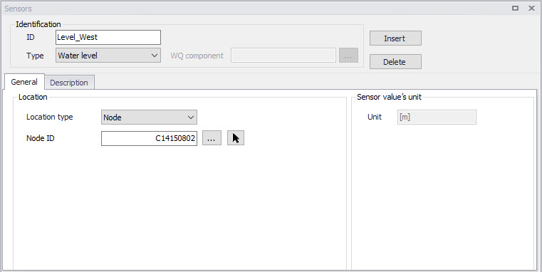
Figure: The Sensors editor showing an example setup for a water level sensor
| Edit field | Description | Used or required by simulations | Field name in data structure |
|---|---|---|---|
| ID | Sensor unique identifier | Yes | MUID |
| Type | Type of parameter measured by the sensor | Yes | TypeNo |
| WQ Component | Measured water quality component | Yes If Type = Concentration or Mass flux | ComponentID |
| Apply | Flag activating or deactivating the sensor in the simulation | Yes | Enabled |
| Location/ Type | Location type | Yes | LocationNo |
| Location/ ID | Location ID | Yes | _LocationID (prefix varies with location type) |
| Time Series File | Path to external time series file defining sensor values | Yes If Type = External | TSFileName |
| Time Series Item | Item name for the selected data series from the time series file | Yes If Type = External | TSItemName |
| Expression | Expression defining a user-defined variable | Yes If Type = Variable expression | Expression |
| Description | Free text description of the sensor | Optional | Description |
Table: Overview of the Sensors editor attributes (Table msm_RTCSensor)
Sensor ID
Each sensor needs a unique ID, which can be used to access the sensor information from other dialogs.
Type
This parameter defines the type of variable measured by the sensor. The options are:
- Level
- Discharge
- Surface Runoff
- Concentration
- Mass Flux
- Weir/Gate Position
- Pump ON/OFF
- Action Active (returns a value TRUE when the selected action is active, and FALSE when it's inactive)
- Action Active Time (returns a TimeSpan, which is the time since it was last activated. It returns zero when the action is not active. It can be turned into hours or seconds using a formula)
- Velocity
- Water depth
- Area (cross sectional / flow area)
- Volume
- Valve Opening
- External (external time series file)
- Variable expression (defines a user-defined variable, e.g. defined as a function of other sensors and mathematical functions).
WQ Component
The measured water quality component for the ‘Concentration’ and ‘Mass Flux’ sensor types.
Apply
This controls whether the sensor is active or not in the simulation. When a sensor is deactivated (i.e. when its 'Apply' check box is unchecked), the sensor is ignored in the simulation and must not be used by any of the active control rules.
The purpose is to deactivate sensors monitoring a part of the network which is also inactive in the simulation (e.g. because a pipe or structure is removed in a scenario, or because the collection system or river network is not included in the simulation) without having to delete the sensor permanently.
Location Type and Location
Depending on the sensor type, various location types are available:
- Node: for this location type, the location is defined with a node ID
- Link: for this location type, the location is defined with a link ID and a chainage
- Structure: for this location type, the location is defined at the location of a selected structure. This location type only applies to Discharge type of sensor.
- Upstream structure: for this location type, the sensor is automatically located at the first calculation point upstream of a structure
- Downstream structure: for this location type, the sensor is automatically located at the first calculation point downstream of a structure
- Reach on link: this type is only available for the Volume type of sensor, and indicates that the volume is to be considered between two chainage values along a link
Define the location type and then specify the corresponding location ID. Note that a ‘location’ may be only indirectly related to a physical location, such as for ‘Action Active’ and ‘External’ sensors.
Time Series File and Item
For an ‘External’ sensor type, an external time series file, which will be used for sensor values, must be defined. Select the appropriate time series Item to use when loading the time series file.
Expression
The expression is used to define an 'Expression variable' sensor. This type of variable is usually a function of other sensors. The primary purpose is to define complex control rules using such variables: instead of defining a complex condition for a control rule, it is possible to define a complex variable and then call it in a simpler condition for the control rule. The variable's value can also be saved in the result file during the simulations, and it is therefore easier to check that the correct behaviour of the regulated structure is modelled, by comparing the applied control strategy with the variable.
The expression defining the mathematical expression of the variable can be typed manually or using the 'Edit' button. This button opens the Expression Editor, which offers a list of available sensors, functions and operators.
Example: An example of a syntax for a variable deriving the energy through a structure may be as provided below:
9.81 * [dh] * [Q] * [efficiency]
Where [Q] is a sensor returning the discharge value through the structure and [dh] and [efficiency] are other user-defined variables.
Note about syntax
The condition must be written with the syntax from C# programming language. Therefore, the few rules below should apply:
- A path to file must be written with double \ For example, if a variable looks up the time series C:\Data\TS.dfs0, the file path in the function must be written C:\\Data\\TS.dfs0.
- The decimal separator must always be a point.
Warning
Circular references (i.e. interdependency of variables) are not supported. That is, a first expression variable can depend on a second one, but in this case it is not allowed that this second variable also depends on the first one. If Variable1 is used in the expression defining Variable2, then Variable1 must be defined above Variable2 in the table. The order of the variables is changed using the 'Move up' and 'Move down' buttons.
Move up / Move down buttons
The order of the sensors in the table is important only for 'Expression variable' sensors, and only in case one variable is defined as a function of another variable.
Unit
The unit is read-only, and is shown for information. It controls in which unit the sensor values are considered in the expressions, for example in the 'Condition' expression of a control rule. The unit is set according to the sensor type. The unit can be changed for each sensor type from the 'Model type' page. Refer to Selecting an Appropriate Unit Environment for more information about units customization.