LID Properties Editor
The MIKE+ LID Properties editor organizes the data input for the different layers and functional elements of LID structures. The input data is organized into the following group and tabs:
- Identification: This group provides unique identification of the specified LID and definition of its type. Each individual LID is generic and is specified per unit area. As such, it can be replicated and placed in any sub-catchment of the study area (i.e. deployed) with different actual sizes and in any number of instances.
- Tabs: Surface, Soil, Pavement, Storage, Drain, and Drainage Mat. These tabs represent different layers and functional elements defining the structure of the LID. The properties of each layer and functional element, which constitute the actual LID type, are entered in these tabs. Only the relevant data fields for a LID type are activated and available for data input.
Identification
| Edit field | Description | Used or required by simulations | Field name in data structure |
|---|---|---|---|
| ID | ID of LID | Yes | MUID |
| Type | Type of LID 1:Bioretention Cell 2:Porous Pavement 3:Infiltration Trench 4:Rain Barrel 5: Vegetative Swale 6:Rain Garden 7:Green Roof | Yes | LIDTypeNo |
Table: The LID Properties Identification Group (Table msm_LIDcontrol)
LID Properties
The various figures below illustrate the six tabs containing the data for various functional elements of LID structures. The corresponding parameter attributes in the msm_LIDcontrol database table are summarised in subsequent tables divided by component following the tabs.
Surface
A Surface component is used for the following LID structures:
- Bioretention Cell
- Porous Pavement
- Infiltration Trench
- Vegetative Swale
- Rain Garden
- Green Roof
Figure: The LID Properties editor Surface tab
| Edit field | Description | Used or required by simulations | Field name in datastructure |
|---|---|---|---|
| Storage Depth | When confining walls or berms are present, this is the maximum depth to which water can pond above the surface before overflow occurs. For LIDs that experience ponding it is the height of any surface depression storage. For swales, it is the height of its trapezoidal cross section. | Yes If LIDTypeNo = (1,2,3,5,7) | StorHt |
| Vegetative Cover | The fraction of the storage area above the surface that is filled with vegetation (0 = no vegetation, 1 = no storage available). NOTE: for infiltration trench, vegetative cover is typically non-existent | Yes If LIDTypeNo = (1,2,3,5,7) | VegFrac |
| Swale Side Slope | Slope (run over rise) of the sidewalls of a vegetative swale´s cross section. Used for the calculation of the stored volume and wetted width. This value is ignored for other types of LIDs | Yes If LIDTypeNo=5 | Xslope |
| Roughness formulation | Selects whether the roughness value is expressed as Manning (M) or Manning (n) | Yes | FricTypeNo |
| Surface Roughness | Manning´s n or M (used in combination with surface slope and width) for routing of overflow from the surface of bioretention cell, rain garden, infiltration trench, porous pavement and for flow routing in vegetative swale (see Table 4.32 for typical values). If specified zero (for all types except vegetative swale), no routing of the overflow is applied | Yes If LIDTypeNo = (1,2,3,5,6,7) | Rough |
| Surface Slope | Slope (used in combination with surface roughness and width) for routing of overflow from the surface of bioretention cell, rain garden, infiltration trench, porous pavement and for flow routing in vegetative swale. If specified zero (for all types except vegetative swale), no routing of the overflow is applied | Yes If LIDTypeNo = (1,2,3,5,6,7) | Slope |
| Soil infiltration capacity | The rate of water moving from surface into the soil. It is characteristics of the surface and the uppermost soil layer (equivalent to Horton´s initial infiltration capacity). Infiltration takes place at all times during a rain event and after, as long as there is water available as rainfall, as run on or as water stored in the surface. | Yes If LIDTypeNo = 5 | InfiltrationCapacity |
Table: LID Properties Surface tab attributes (Table msm_LIDcontrol)
Soil
A Soil component is used for the following LID structures:
- Bioretention Cell
- Rain Garden
- Green Roof
Figure: The LID Properties editor Soil tab
| Edit field | Description | Used or required by simulations | Field name in datastructure |
|---|---|---|---|
| Thickness | Thickness of the soil layer. Typical values range from 450 to 900 mm for rain gardens, street planters and other types of land-based bioretention units, but only 75 to 150 mm for green roofs | Yes If LIDTypeNo = (1, 5, 6, 7) | SThick |
| Porosity | Volume of pore space relative to total volume of soil (as a fraction) | Yes If LIDTypeNo = (1, 5, 6, 7) | Por |
| Field Capacity | Volume of pore water relative to total volume held in the soil after excess water has drained away and the rate of downward movement has decreased (as a fraction). Vertical percolation of water through the soil occurs only when field capacity level is reached or exceeded. | Yes If LIDTypeNo = (1, 5, 6, 7) | FC |
| Wilting Point | Volume of pore water relative to total volume for a well-dried soil where only bound water remains (as a fraction). The moisture content of the soil cannot fall below this limit and wilting point cannot be higher than the Field Capacity level. | Yes If LIDTypeNo = (1, 5, 6, 7) | WP |
| Leakage Capacity | The rate of water leaving the soil layer into storage. It is characteristic of the soil layer. Leakage starts when soil storage exceeds field capacity, continues at all times while soil storage is above the field capacity. | Yes If LIDTypeNo = (1, 5, 6, 7) AND FlowMethod = 1 (Capacity-based) | LeakageCapacity |
| Infiltration Capacity | The rate of water moving from surface into the soil. It is characteristics of the surface and the uppermost soil layer (equivalent to Horton´s initial infiltration capacity). Infiltration takes place at all times during a rain event and after, as long as there is water available as rainfall, as run on or as water stored in the surface. | Yes If LIDTypeNo = (1, 5, 6, 7) | InfiltrationCapacity |
| Conductivity | Hydraulic conductivity for the fully saturated soil. This is equivalent to leakage capacity | Yes If LIDTypeNo = (1, 5, 6, 7) AND FlowMethod = 2 (conductivity based)) | Ksat |
| Conductivity Slope | Slope of the curve of log (conductivity) versus soil moisture content (dimensionless). Typical values range from 5 for sands to 15 for silty clay | Yes If LIDTypeNo = (1, 5, 6, 7) AND FlowMethod = 2 (Conductivity-based) | Kcoeff |
| Suction Head | The average value of soil capillary suction along the wetting front. This is the same parameter as used in the Green-Ampt infiltration model | Yes If LIDTypeNo = (1, 5, 6, 7) AND FlowMethod = 2 (Conductivity-based) | Suct |
Table: LID Properties Soil tab attributes (Table msm_LIDcontrol)
Pavement
A pavement component is used for the following LID type:
- Porous Pavement
Figure: The LID Properties editor Pavement tab
| Edit field | Description | Used or required by simulations | Field name in datastructure |
|---|---|---|---|
| Thickness | Thickness of the pavement. Typical values are 100 to 150 mm | Yes If LIDTypeNo = 2 | PThick |
| Porosity | The ratio (expressed as a fraction) of the volume of the pores or interstices of a material to the total volume of the pavement. Typical values range from 0.11 to 0.17 for pavements Note that porosity = void ratio/(1 + void ratio). | Yes If LIDTypeNo =2 | PVPorosity |
| Permeability | Permeability of concrete or asphalt used in continuous systems or hydraulic conductivity of the fill material (gravel or sand) used in modular systems. Permeability of new porous concrete or asphalt is high (>2450 mm/h), but over time the fine particles in the runoff tend to clog the pavement, reducing the permeability of the structure. | Yes If LIDTypeNo = 2 | Perm |
| Impervious Surface | Ratio of impervious paver material to total area for modular systems; 0 for continuous porous pavement systems | Yes If LIDTypeNo = 2 | FracImp |
| Clogging Factor | Voids that are clogged due to fine particles accumulation, as a fraction of total voids area. Use a value of 0 to ignore clogging. Max. value = 1. | Yes If LIDTypeNo = 2 | PVClog |
Table: LID Properties Pavement tab attributes (Table msm_LIDcontrol)
Storage
A Storage component is used for the following LID structures:
- Bioretention Cell
- Porous Pavement
- Infiltration Trench
- Rain Barrel
Figure: The LID Properties editor Storage tab
| Edit field | Description | Used or required by simulations | Field name in datastructure |
|---|---|---|---|
| Height | The height of the storage layer in case of bioretention cell, porous pavement and infiltration trench; the height of a rain barrel (mm or inches). Crushed stone and gravel layers are usually 150 to 450 mm thick while rain barrels vary in height from 600 mm upwards. | Yes If LIDTypeNo = (1,2,3,4) | Height |
| Porosity | The ratio of the volume of the pores or interstices of a material to the total volume of the layer. Typical values range from 0.30 to 0.45 for gravel beds. Note that porosity = void ratio/(1 +void ratio). | Yes If LIDTypeNo = (1,2,3) | SVPorosity |
| Conductivity | The maximum rate at which water infiltrates to the surrounding soil through the bottom of the freshly constructed storage layer. | Yes If LIDTypeNo = (1, 2, 3) | Filt |
| Clogging Factor | Volume of voids that are clogged due to fine particles accumulation. Use a value of 0 to ignore clogging. | Yes If LIDTypeNo = (1,2,3) | SVclog |
Table: The LID Properties Storage tab attributes (Table msm_LIDcontrol)
Drain
A Drain component is used for the following LID structures:
- Bioretention Cell
- Porous Pavement
- Infiltration Trench
- Rain Barrel
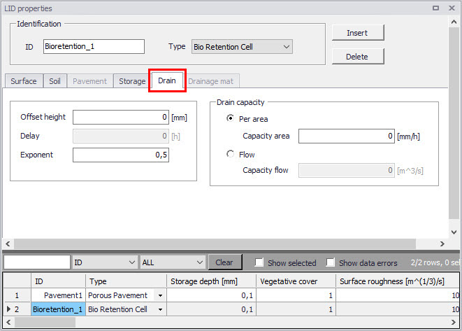
Figure: The LID Properties editor Drain tab
| Edit field | Description | Used or required by simulations | Field name in datastructure |
|---|---|---|---|
| Offset Height | Height of any underdrain piping above the bottom of a storage layer or rain barrel | Yes If LIDTypeNo = (1,2,3,4) | HOffset |
| Delay | The number of dry weather hours that must elapse before the drain in a rain barrel is activated | Yes If LIDTypeNo = 4 | Delay |
| Exponent | Exponent n that determines the rate of flow through the underdrain as a function of height of stored water above the drain height. | Yes If LIDTypeNo = (1,2,3,4) | Expon |
| Capacity Area | Coefficient that determines the rate of flow through the underdrain as a function of height of stored water above the drain bottom. Expressed in terms of flow capacity per area. | Yes If LIDTypeNo = (1,2,3,4) AND Drain Capacity = Per Area | DrainCapacityArea |
| Capacity Flow | Coefficient that determines the rate of flow through the underdrain as a function of height of stored water above the drain bottom. Expressed in terms of flow capacity. | Yes If LIDTypeNo = (1,2,3,4) AND Drain Capacity = Flow | DrainCapacityFlow |
Table: The LID Properties Drain tab attributes (Table msm_LIDcontrol)
Drainage Mat
A Drainage Mat component is used for the following LID structure:
- Green Roof

Figure: The LID Properties Editor Drainage Mat tab
| Edit field | Description | Used or required by simulations | Field name in datastructure |
|---|---|---|---|
| Thickness | The thickness of the mat or plate. It typically ranges between 25 to 50 mm | Yes If LIDTypeNo = 7 | DMThick |
| Porosity | The ratio of void volume to total volume in the mat. It typically ranges from 0.5 to 0.6 | Yes If LIDTypeNo = 7 | DMVPorosity |
| Roughness formulation | Selects whether the roughness value is expressed as Manning (M) or Manning (n) | Yes | DMFricTypeNo |
| Roughness | Manning´s number, used to compute the horizontal flow rate of drained water through the mat. In absence of standard product specifications provided by manufacturers, the roughness must be estimated. Use of n values from 0.1 to 0.4 (M = 2.5 - 10) is suggested. | Yes If LIDTypeNo = 7 | DMRough |
Table: The LID Properties Drainage Mat tab attributes (Table msm_LIDcontrol)
The table below shows examples of Manning M values for different types of surfaces.
| Surface type | Manning M |
|---|---|
| Smooth asphalt | 91 |
| Smooth concrete | 83 |
| Ordinary concrete lining | 77 |
| Good wood | 71 |
| Brick with cement mortar | 71 |
| Vitrified clay | 67 |
| Cast Iron | 67 |
| Corrugated metal pipes | 42 |
| Cement rubble surface | 42 |
| Fallow soils (no residue) | 20 |
| Cultivated soils | 50 to 20 |
| Residue cover < 20% | 17 |
| Residue cover > 20% | 6 |
| Range (natural) | 8 |
| Short, prairie | 7 |
| Dense | 4 |
| Bermuda grass | 2 |
| Woods | 10 |
| Light underbrush | 2,5 |
| Dense underbrush | 1,25 |
Table: Manning´s M of surface for porous pavement or vegetative swale (Source: McCuen, R. et al. (1996), Hydrology, FHWA-SA-96-067, Federal Highway Administration, Washington, DC)
The table below shows hydraulic conductivity properties for various porous media.
| Material | Hydraulic conductivity K (cm/s) | Porosity h (%) |
|---|---|---|
| Gravel | \(10^{-1} - 10^{2}\) | 25 - 40 |
| Sand | \(10^{-5}\) – 1 | 25 - 40 |
| Silt | \(10^{-7}- 10^{-3}\) | 35 - 50 |
| Clay | \(10^{-9} - 10^{-5}\) | 40 - 70 |
Table: Hydraulic conductivity and porosity of unconsolidated porous media (Source: Freeze, R.A., and Cherry, J.A., (1979), Groundwater, Prentice-Hall, Englewood Cliffs, NJ)