Pumps
A pump controls the discharge on a river between two cross sections, either using a constant discharge or a relationship between its discharge and the upstream/downstream water level difference.
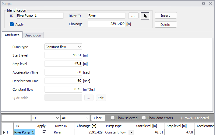
Figure: The Pumps editor accessed via the River Network setup group
Identification
The Identification group holds basic information on pumps structures.
ID
Unique string identification for the pump.
River ID
The ID of the river where the pump is located. The River ID is automatically registered if the pump is created via the Map. Use the button with an arrow, to select the location of the structure on the map: this will specify both the River ID and the Chainage of the structure.
Chainage
Chainage at which the pump is located along the river.
Apply
This check box allows the user to toggle the Active status of the pump on and off. The simulations will omit all pumps that are not active.
Attributes
The general settings of the pumps are defined on the Attributes tab of the pumps editor.
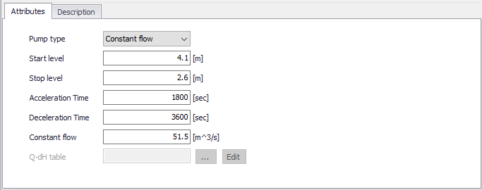
Figure: Attributes tab on the Pumps editor
Pump type
The pump type is determined by the way its pump rate or discharge is defined:
- Constant flow: Pump discharge is fixed and independent of the local water head except for the start/stop control.
- Q-DeltaH: Pump discharge is controlled by a specified relationship between the discharge Q and the water level difference (dH).
Start level
The pump will be activated when the upstream water level exceeds the Start level.
Stop level
Water level below which the pump starts closing down
Acceleration time
Duration for changing pump discharge from zero to full flow. The pump discharge is changed linearly in time.
Deceleration time
Duration for changing pump discharge from full flow to zero. The pump discharge is changed linearly in time.
Constant flow
The fixed discharge value, when the pump type is 'Constant flow'.
Q-dH table
The selected table holding the relationship between the pump discharge Q and the upstream/downstream water level difference (dH). The table must be defined in the 'Curves and relations' editor, with a type 'Capacity Curve QdH'. Use the '…' button to select a table among the existing tables with a valid type. The discharge is determined through interpolated look up in the table.
Note
Extrapolation is not allowed. It is therefore recommended to add limit points to the Q-dH curve.
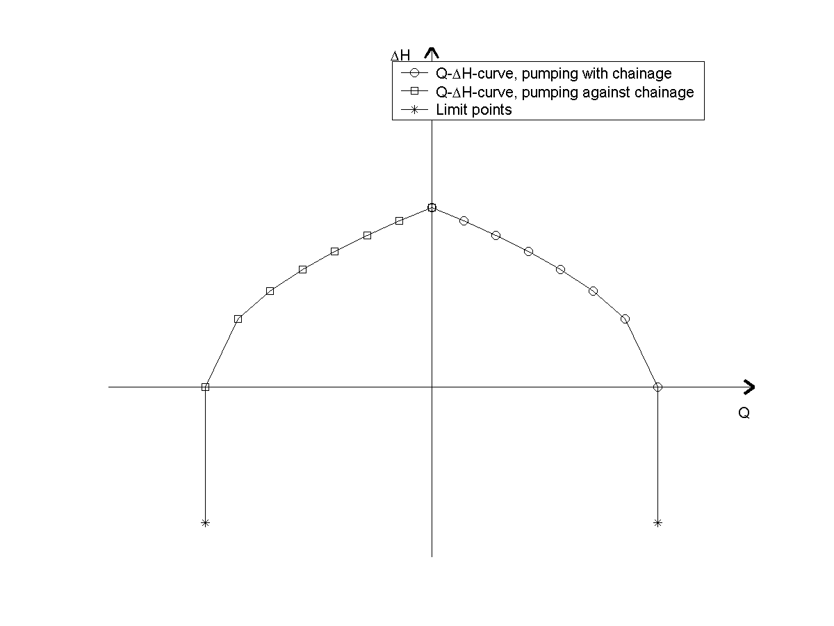
Figure: Q-dH curves for pumps
Note
A positive discharge Q is always interpreted as the pump pumping from upstream to downstream (i.e. from higher lying areas to a lower lying areas). Typically, this is from smaller chainage to higher chainage. If a negative flow direction is selected for the river containing the pump, positive discharge is still interpreted as pumping from upstream to downstream, but in this situation it means pumping from higher chainages to smaller chainages.
Description
Use the Description tab to add free text descriptions for pumps. It offers options for providing model management information, as well as attributes for quick model data query.
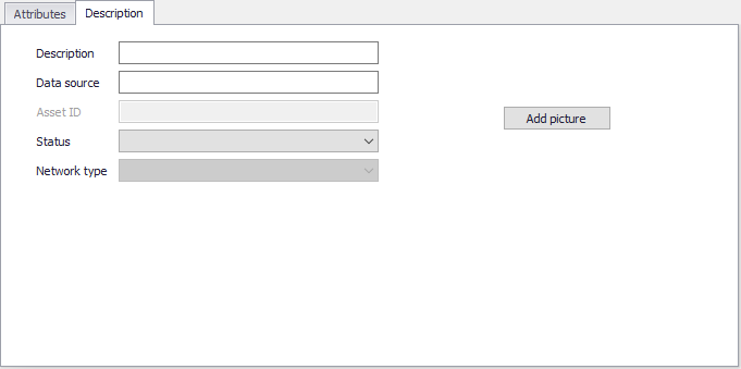
Figure: The Description tab on the Pumps editor
- Description: Free text description for the pump.
- Data source: Free text describing data source for pump data.
- Status: Project-defined status information that may be used for model build management or e.g. model data query. Pre-defined codes are contained in the Status Code editor which may be accessed via the ellipsis button from the Status dropdown menu.
- Add picture: Option for adding images associated with the pump.