Energy losses
An energy loss is used to define losses associated with local flow obstructions such as sudden flow contractions or expansions and gradual or abrupt changes in the river alignment. Moreover, a user defined energy loss coefficient can be defined.
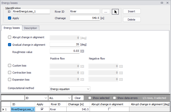
Figure: The Energy losses editor accessed via the River Network setup group
Identification
The Identification group holds basic information on energy losses.
ID
Unique string identification for the energy loss.
River ID
The ID of the river where the energy loss is located. The River ID is automatically registered if the energy loss is created via the Map. Use the button with an arrow, to select the location of the structure on the map: this will specify both the River ID and the Chainage of the structure.
Chainage
Chainage at which the energy loss is located along the river.
Apply
This check box allows the user to toggle the Active status of the energy loss on and off. The simulations will omit all energy losses that are not active.
Energy losses
At each specified energy loss location, a discharge grid point is inserted at simulation time. At each time step of the computation, the discharge at energy loss points is computed by use of the energy equation:
(3.6) 
in which DH is the energy loss, g is the acceleration of gravity, Q is the discharge, A is the cross-sectional wetted area and z denotes the energy loss coefficient.
Five different types of energy losses may be included in the simulation:
- Abrupt change in alignment
- Gradual change in alignment
- Custom loss
- Contraction loss
- Expansion loss
For an alignment change, the angular change in river alignment at the energy loss point must be specified. Additionally, for a gradual change the roughness coefficient must be defined.
For a custom loss, contraction loss or expansion loss, an energy loss coefficient must be defined for both positive and negative flows.
Besides, a computational method must be selected. Two options are available:
- Energy equation: with this method, the flow through the structure is solved using the energy equation, in order to compute the discharge in the structure as a function of the head loss factors. The computed discharge is then applied at the calculation point. This is the preferred option in case there are big changes in cross sections at an obstacle, or if the flow area alongside the obstacle is much less than that of the river.
- Shallow water equation: with this method, the flow through the structure is solved adding a head loss term to the shallow water equation (Saint-Venant momentum equation), this term being a function of the head loss factors. With this method, the same equation is applied at structures' locations as at other regular calculation points (without structures). This ensures a continuity of the results between the upstream / downstream reaches and the structure, e.g. also including a bed friction between the upstream and downstream cross sections of the structure. Additionally, this method also enforces the use of velocity in upstream and downstream cross sections to compute the head loss, instead of using the velocity in the structure. and downstream cross sections to compute the head loss, instead of using the velocity in the structure. This option is mainly designed for scenarios where a structure creates little or no head loss for low water levels. See the "Head loss mode" in the MIKE 1D reference manual, for more information.
Note
When the flow through the structure becomes supercritical, the applied method is always the Energy equation. Besides, the 'Shallow water equation' method cannot be applied for structures located on rivers of type 'Structure link'. When several structures exist at the same location, if any of them uses the Shallow water equation method, then all other structures at the same location will also apply the same equation no matter the selected method in their properties.
Description
Use the Description tab to add free text descriptions for energy losses. It offers options for providing model management information, as well as attributes for quick model data query.
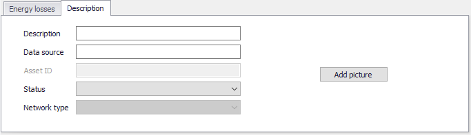
Figure: The Description tab on the Energy losses editor
- Description: Free text description for the energy loss.
- Data source: Free text describing data source for energy loss data.
- Status: Project-defined status information that may be used for model build management or e.g. model data query. Pre-defined codes are contained in the Status Code editor which may be accessed via the ellipsis button from the Status dropdown menu.
- Add picture: Option for adding images associated with the energy loss.