Data Input
LTS Job List
LTS Job list specifies intervals within the LTS simulation period that are relevant for dynamic network simulation. Duration of each job (i.e. simulation event) is defined by its START time and END time.
A job list is generated by the LTS computational engine on the basis of model setup and boundary files, the simulation period (specified in the Simulation Setup Editor, General tab), optionally the LTS initiation hot start file(s) and user-specified job list criteria.
The job list is written into an ASCII file, recognizable by the extension *.jlf.
The job list file includes the following information:
- General information on the actual simulation setup
- List of relevant boundary conditions
- Overview over job list criteria
- Job list events, defined by
- Start time
- End time
- Hot start file name and hot start time
- Triggering job list criteria
- Job List Summary
Job List Criteria
Job list criteria are defined as hydraulic loads thresholds on the network, including dry weather flow (i.e. wastewater), rainfall and other loads, with the purpose of identifying and delimiting wet weather periods relevant for dynamic (network) simulation. Each job list criterion consist of a job START criterion and a job STOP criterion.
Job START criterion selects rainfall events to be included in the LTS job list, by comparing the inflow generated by all hydraulic loads to the specified part of the model (location) with the specified start-threshold value: if the threshold is exceeded continuously for at least the specified duration, the event is included in the job list. The simulation event start time is set at exactly the beginning of the identified rainfall event.
The location can be specified as an individual node, part of the system defined by a selection list or the system as the whole (General).
The START threshold value should be specified as an estimate of the hydraulic load peak just below the load that is likely to cause the operational effects of interest (e.g. overflows, inundations, activation of retention basins, etc.). By these means, many small, potentially irrelevant rainfall events are eliminated from the LTS simulation, making it feasible and time-efficient. Anyway, the specified threshold should be set sufficiently low to ensure that none of the relevant events is omitted from the simulation.
"Duration" is included in the evaluation to avoid inclusion of very short events that, despite a relatively high peak, are not likely to cause significant hydraulic effects in the system.
If multiple job list criteria are specified and activated, at least one active START criterion must be fulfilled for the event to be included in the job list.
Job STOP criterion defines the anticipated end of dynamic simulation (i.e. end-time of the simulation event). The end-time is set by comparing the inflow generated by all hydraulic loads to the specified part of the model with the specified end-threshold value: simulation end-time is set at the time when the load falls below the specified threshold and remains lower than the threshold continuously for at least the specified duration.
The simulation event end time may be extended by (optional) runtime stop criteria.
"Duration" ensures that very short drops in inflow are ignored, i.e. that the inflow load has definitely dropped below the threshold. Also, appropriately set "duration" may secure that the time offset between the actual hydraulic load and its effects in the system is included in the dynamic simulation. In the large systems including significant volumes, this offset may be quite long (e.g. emptying od a large retention basin may take many hours or even days). In such cases, instead of attempting to capture this by setting a long duration for the job list stop criterium, runtime criteria should be applied.
If multiple job list criteria are specified and activated, all active STOP criteria must be fulfilled at the simulation event end-time.
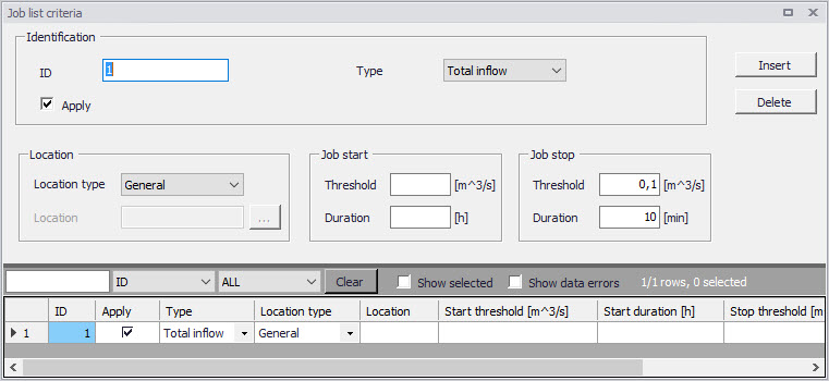
Figure: The Job List Criteria editor
LTS simulation requires definition of at least one set of job list criteria
| Edit field | Description | Used or required by simulation | Field name in data structure |
|---|---|---|---|
| ID | Job list criteria identifier. Up to 40 characters and case sensitive. | Yes | MUID |
| Type | Controls the type of criterion to be specified. In this version only “Total Inflow” can be selected | Yes | ConditionNo |
| Apply checkbox | Checkbox for activating or deactivating a Job list criteria | Yes | ApplyNo |
| Location Type | For the criteria of type ‘Total Inflow’, it must be specified for which part of the system the inflow must be evaluated. ‘Location type’ can be: ‘General’ (the whole system), ‘List’ (a list of elements), or ‘Individual’ (a single node) | Yes | LocationNo |
| Location | For the types ‘List’ and ‘Individual’, additional information must be specified in the ‘Location’ field. For the ‘List’, a Selection List must be specified. For ‘Individual’, a single node name must be types or selected from the node list. | Yes, except LocationNo=1 (General) | LocationID |
| Job Start Threshold | Defines the threshold that must be exceeded in order to evaluate the job start criterion as true. | Yes | StartValue |
| Job Start Duration | Criteria of type ‘Total Inflow’ can optionally be extended by specifying the duration of a continuous period in which the threshold must be exceeded in order to evaluate the criterion as true. The Default duration is zero. | Yes | StartTime |
| Job Stop Threshold | Defines the lower threshold that must be achieved in order to evaluate the job stop criterion as true. | Yes | StopValue |
| Job Stop Duration | Specifies the duration of a continuous period in which the stopping threshold must be fulfilled in order to evaluate the stop criterion as true. The Default duration is zero. | Yes | StopTime |
Table: Job List Criteria editor attributes (Table msm_LTSJobListCriteria)
Initial Conditions for Simulated Events
Appropriate initial conditions for the individual LTS simulation events are essential for achieving realistic statistics in hydrodynamic LTS simulations.
LTS provides two different methods for initializing the network model: The network model can either be initialized in an empty state before each job (Default), or a set of hot start files can be provided. If the latter option is used, then the specific hot start file used for a simulation event is selected based on the actual hydrological inflow to the system at the start of the event.
When applying the 'Empty system' method, the model will for all simulated events be initiated as empty, similarly as in a normal network simulation without hot start. This option is valid only for storm drainage systems where there is no water in the system during dry periods. It is not recommended to use this option in any other situation.
The method with hot start accounts for the correct initial conditions related both to the amount of infiltration and DWF load at the simulation event start time.
If a set of hot start files is provided, each hot start file must be associated with an inflow interval for total hydrological inflows. This interval is the "validity interval", meaning that the specified hot start file is valid (i.e. the file will be used) for all simulation events in the Job List where the total hydrological inflow (i.e. inflow generated by any of the hydrological models) to the network at the beginning of the actual simulation event is within that interval.
Note
For the surface runoff models, the hydrological inflows will be zero at the beginning of the simulation event in most cases. This implies that correct initial conditions may be achieved with only one hot start file, covering any possible inflow, defined as the inflow interval including zero inflow (e.g. from 0 \(\text{m}^{3}/\text{s}\) to 10 \(\text{m}^{3}/\text{s}\)). This hotstart file is created by simulating the system loaded by any recurring (typically wastewater) loads, over at least one day.
In model setups including continuous hydrological models (RDI), multiple hot start files are needed in order to cover different infiltration levels that may occur at the start of a simulation event. E.g. if it is known that infiltration may vary between zero and 2 \(\text{m}^{3}/\text{s}\), a set of 4 hotstart files may be prepared, covering the following infiltration intervals: 0 → 0.5 \(\text{m}^{3}/\text{s}\), 0.5 → 1.0 \(\text{m}^{3}/\text{s}\), 1.0 → 1.5 \(\text{m}^{3}/\text{s}\), 1.5 → 2.0 \(\text{m}^{3}/\text{s}\). These files are created by simulating the system loaded by any recurring (typically wastewater) loads and constant infiltration loads of 0.25 \(\text{m}^{3}/\text{s}\), 0.75 \(\text{m}^{3}/\text{s}\), 1.25 \(\text{m}^{3}/\text{s}\) and 1.75 \(\text{m}^{3}/\text{s}\), over at least one day. The infiltration loads should be distributed proportionally to the catchment area.
If the total inflow to the system at the beginning of job is outside of all specified validity intervals provided for the hot start files, the system will be initialized with the hot start file that is the closest to the actual inflow.
In order to account for diurnal inflow variations, the time-of-day at which the values from the hot start file should be used is set equal to the simulation event start time. However, the hot start date must be provided by the user. This is because the hot start file may cover two or more days, including the system filling phase. The date specified for the hot start must relate to the day following the completion of the filling phase.
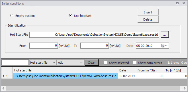
Figure: Initial Conditions editor
| Edit field | Description | Used or required by simulation | Field name in data structure |
|---|---|---|---|
| Empty System/Use Hotstart radio button | Radio buttons for selecting the initial conditions mode | Yes | - |
| Hotstart File | Specifies a hot start file to be used for the system initialization in association with the specified range of total inflows (excluding DWF) detected at the beginning of certain job. | Yes, if Hotstart | HotStartFilename |
| From | Defines a lower threshold for total inflow intervals (excluding DWF) used at the start of each job in the Job List to evaluate what hot start parameters to use. | Yes, if Hotstart | InitFrom |
| To | Defines an upper threshold for total inflow intervals (excluding DWF) used at the start of each job in the Job List to evaluate what hot start parameters to use. | Yes, if Hotstart | InitTo |
| Date | Specifies the date in the hot start file to be used in the search for the hot start conditions associated with the specified range of total inflows (excluding DWF) detected at the beginning of a job. | Yes, if Hotstart | InitDate |
Table: Initial Conditions editor attributes (Table msm_LTSInit)
Generating and editing Job Lists
A Job List is created based on the Job List Criteria, simulation input files, simulation period (specified in the Simulation Setup Editor, General Tab) and, optionally, the LTS initiation hot start file.
A Job List is created using the Create Job List function in the Simulation Setup Editor (Simulation Setup | LTS Tab).
The simulation periods for individual events in the resulting Job List represent the minimum simulation time (i.e. preliminary), which may be extended during run time when evaluating the Run Time Criteria.
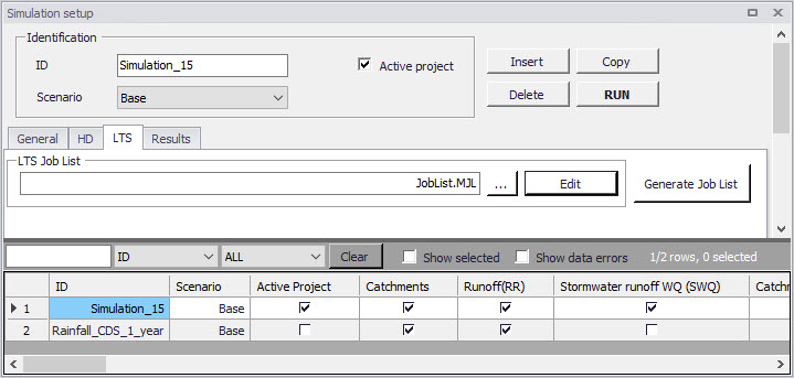
Figure: Generate Job List option in the Simulation Setup Editor LTS tab
There is no dedicated dialog available for reviewing and editing job list files. Instead, Windows Notepad is used. Alternatively, any ASCII editor can be used.
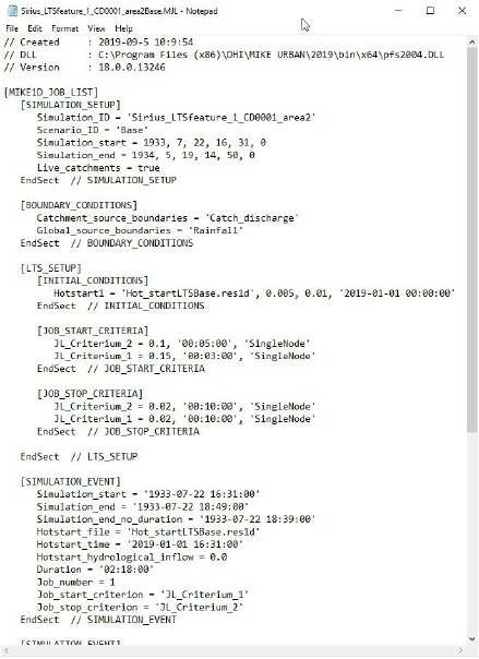
Figure: Example Job List file
Optionally, the Job List file can be edited before starting the LTS calculation.
A job list file includes several info sections:
- SIMULATION_SETUP
- BOUNDARY_CONDITIONS
- LTS_SETUP
- SUMMARY
Actual simulation events are defined in sections "SIMULATION_EVENT" (one section for each event). See example:
[SIMULATION_EVENT]

      Simulation_sTart = '1933-07-22 16:31:00'

      Simulation_end = '1933-07-22 18:49:00'

      Simulation_end_no_duration = '1933-07-22 18:39:00'

      Hotstart_file = 'Hot_startLTSBase.res1d'

      Hotstart_time = '2019-01-01 16:31:00'

     Hotstart_hydrological_inflow = 0.0

      Duration = '02:18:00'

     Job_number = 1

      Job_start_criterion = 'JL_Criterium_1'

      Job_stop_criterion = 'JL_Criterium_2'

     DtMin = 10.0

     DtMax = 10.0

EndSect  // SIMULATION_EVENT
Some of the parameters in the simulation event definition may be edited:
- Simulation_start: defines start time of the simulation event,
- Simulation_end: defines end time of the simulation event,
- Simulation_end_no_duration: defines end time of the simulation event, without "duration". This is of relevance when run-time criteria are included, i.e. defines the time when evaluation of run-time criteria commences.
- Hotstart_file: name of the hot start file for the actual simulation event
- Hotstart_time: hot start time for the actual simulation event
- DtMin: minimum time step [s] for network simulation in the actual simulation event
- DtMax: maximum time step [s] for network simulation in the actual simulation event
The remaining parameters are for information only, and editing would not affect the simulation.
Run Time Stop Criteria
The simulation event end time may optionally be subject to further evaluation and possible extension by a set of Run Time Criteria during the simulation.
Run time Criteria are founded on the evaluation of the operational variables within the network itself, which can potentially extend the simulation beyond the end time defined in the Job List. Since the Run Time Criteria are evaluated during the simulation, it is not possible to determine the exact duration of the dynamic simulation in advance.
LTS Run Time Stop Criteria define threshold values to be evaluated during computations (i.e. run time) in order to determine the earliest time at which the simulation can be stopped without missing important information in the closing phase of the simulated event. This may include e.g. emptying of retention basins and, generally, return of the system to dry weather situation.
The following types of Run Time Stop criteria are available:
- Outflow - Inflow
- The threshold value represents an absolute value of a difference between the total inflow into the system and the total outflow from the system. During rain events, this difference is relatively big due to the dynamic effects in the network: outflows are normally attenuated and delayed in the network. In dry weather, this difference is typically very small and relates to the attenuation and transport time of diurnally varying wastewater loads.
- This criteria is defined for the entire system only (Location = General). It is used to identify return of the system to dry weather situation.
- Outflow
- The threshold value represents outflow from the system at a specified location. The location can be specified as general, list and individual, separately for various types of outlets (outlets, pumps, weirs, orifices, valves).
- This criterium can be used to identify return of the system to dry weather situation, end of overflow, end of pumping from a retention basin, etc.
- Total volume
- The threshold value represents volume of water contained in the model elements specified as location. The location can be specified as general, list and individual.
- Knowing the water volume in the specified location in dry weather situation, this criterium can be used to identify return of the system to dry weather situation, completed emptying of a basin, etc.
- Filling degree
- The threshold value represents the filling degree (fraction of full system volume) of entire system.
- This criterium can be used to identify return of the system to dry weather situation, end of overflow, etc.
- Depth
- This threshold represents water depth in a node specified as location. If location is specified as List of nodes, then the highest depth in all included nodes is evaluated against the specified threshold.
- This criterium can be used to identify completed emptying of a retention basin.
- Local flow
- This threshold represents flow at a specified individual conduit (link) or structure (weir, orifice, pump, valve) anywhere in the system, i.e. not limited to outlets.
The "Duration", associated with each run time criteria, ensures that the criterium has been fulfilled continuously over the specified duration, and that it is not just a short instance in oscillating or varying variable.
The Run Time Stop Criteria for the event being simulated are evaluated throughout the simulation. As soon as some of run time criterium is fulfilled, the time counter for the specified duration is activated. The simulation will stop only after all active run time criteria are fulfilled, but never before the "Simulation_end" time specified in the job list.
For better understanding, figures below illustrate possible situations.
In the depicted example, three active job list criteria are specified (JL1, JL2 and JL3), each with different "duration" parameter. During job list generation, the LTS engine has determined the simulation start time (equal for all three criteria, if the rainfall event exceeds the thresholds specified for all three criteria). Also, the simulation end times are determined for each criterium. The latest of the three "simulation end" times (JL2) is selected and written in the job list.
During the simulation, the three run time criteria (RT, RT2 and RT3) are continuously evaluated. Whenever one of the run time thresholds has been achieved, the duration counter for that criterium is activated. The simulation continues at least until the "simulation_end". If at that time there are any run time criteria still not fulfilled (including the specified duration), the simulation will continue until all run time criteria are satisfied.
In example 1 (figure below), when the simulation reaches the "job list simulation end", the run time criterium RT2 is still not fulfilled for the specified "duration". Therefore, the simulation continues beyond the "job list simulation end" and stop only after RT2 criterium has been satisfied.
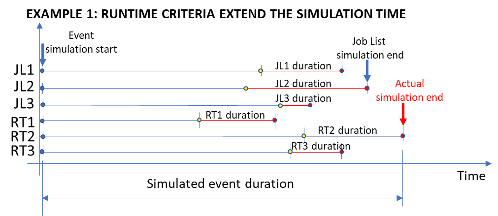
Figure: Run Time criterium RT2 extends the simulation end time determined by job list
In example 2 (figure below), all the run time criteria (including duration) have been satisfied before the simulation reaches the "job list simulation end". Therefore, the simulation ends at the "job list simulation end".
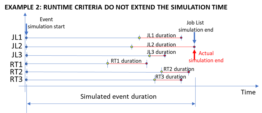
Figure: Run time criteria do not affect the "job list simulation end"
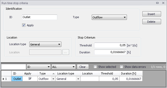
Figure: The Run Time Stop Criteria editor
| Edit field | Description | Used or required by simulation | Field name in data structure |
|---|---|---|---|
| ID | Unique name for a Run Time Stop criterion Each criterion is identified with a unique indentifier, which is used as a reference in the evaluation matrix. | Yes | MUID |
| Type | Controls the type of criterion to be specified: - Inflow-Outflow (difference between inflow and outflow), - Outflow (total outflow), - Total Volume (total volume stored in the system), - Filling degree (filling degree in the system), - Depth, - Local flow | Yes | ConditionNo |
| Apply checkbox | Checkbox for activating or deactivating a Run Time Stop Criteria set | Yes | ApplyNo |
| Location Type | Defines for which part of the system the run time stop criteria must be evaluated. Location type can be: - General (the whole system), - List (a list of elements), - Node, - Outlet, - Weir, - Orifice, - Pump, - Valve, - Link | Yes | LocationNo |
| Location | For the ‘List’ Location Type, a Selection List must be specified. For individual element location types, a single element ID must be specified or selected from the element list. | Yes, Except for Location Type = General | LocationID |
| Threshold | The residual value of the variable defined by the ‘Type’ that must be achieved in order to evaluate the criterion as true | Yes | StopValue |
| Duration | A period in which the parameter value must be below the threshold in order to evaluate the criterion as true. | Yes | StopTime |
Table: Run Time Stop Criteria database attributes (Table msm_LTSRunS)
LTS Global Parameters - Event Definitions
In terms of events statistics, MIKE+ LTS distinguishes events associated with extremes (maxima) of instantaneous variables (e.g. water level, discharge, mass transport), and intermittent (i.e. discontinuous) events where accumulated values (e.g. volume, pollution mass) and durations are calculated.
In order to perform statistical analysis on extreme events (maxima), MIKE+ LTS analyses the respective time series and identifies independent extreme events. For instantaneous variables (e.g. water level, discharge, concentration, etc.), the event identification must consider time between consecutive extreme events and the "depth" of the local minima in order to eliminate dependent maxima and "noise" caused by numerical instabilities, a nearby pump action, etc. In other words, MIKE+ LTS applies two interevent criteria to identify independent extreme events:
- Interevent time criterion \(dT_{c}\): Two successive events (i.e. peak occurrences) are considered independent if the time between the two events is larger than \(dT_{c}\). This parameter is considered for all statistics of instantaneous values, i.e. level, flow, velocity, and concentration.
- Interevent level criterion \(p_{c}\) (0 < \(p_{c}\) < 1): Two successive events are independent if the level between the events is smaller than pc times the lower of the two events. This is a threshold for the ratio between the lowest minimum value between two peaks and the lower peak.
MIKE+ LTS considers two successive events as independent only if both criteria (1) and (2) are fulfilled. This means that two peaks are independent if the time between them is longer than \(dT_{c}\) AND if the lowest minimum between the two peaks is smaller than the value of the smaller peak multiplied with \(p_{c}\).
Both for peak statistics and for accumulated flow statistics, two events are always considered as independent if the computation has been stopped in between by the specified stop criteria. Thus, specification of a very long dT - longer than any individual event to be simulated would result in the number of peak values and the number of accumulated discharges and duration corresponding exactly to the number of simulated events.
Each MIKE+ LTS simulation job contains at least one statistical event. In some cases, several events may be identified within one MIKE+ LTS Job.
The interevent time criterion \(dT_{c}\) is user-specified through the LTS Global Parameters editor, separately for instantaneous (Q, H, v, C) and accumulated (V, T, M) values. The interevent level criterion pc is also specified through the LTS Global Parameters editor.
Note
The default value 0.75 only removes "noise" of relatively small amplitude as well as prevents false extremes in case of a flat time series. Application of smaller values would reduce the number of identified independent events.
Note
For some variables (e.g. discharge) the specified pc applies for the actual value of the variable. In other cases, e.g. water levels, pc is applied on local water depth, i.e. water level subtracted local invert level. In principle, all variables are offset so that the minimum possible local value is zero.
Definition of independent extreme events for instantaneous variables is illustrated in several examples below.
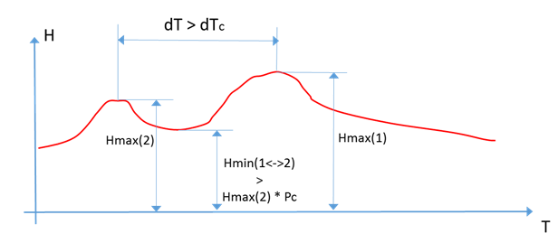
Figure: The two water level (i.e. depth) peaks in the time series are grouped under one event. The higher of the two depth peaks is clearly one extreme event in the current simulation. The other peak (Hmax(2)) is also a candidate for extreme depth event, because it occurs before the highest peak longer that the specified dTc criterion. But evaluation of the level criterion is negative - the "bottom" between the two peaks is higher that the specified criterion pc. Therefore, Hmax(2) is not considered a separate, independent event and is considered as belonging to the same event leading to the true peak Hmax(1).
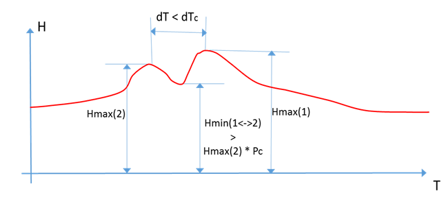
Figure: The two water level (i.e. depth) peaks in the time series are grouped under one event. The higher of the two peaks is clearly one extreme event in the current simulation. The other peak (Hmax(2)) is also a candidate for extreme depth event, but evaluation of both criteria is negative - this peak occurs too close to the highest peak and the "bottom" between the two peaks is higher that the specified criterion pc. There- fore, Hmax(2) is excluded as a separate, independent event. Rather, it is considered as belonging to the same event leading to the true peak Hmax(1).
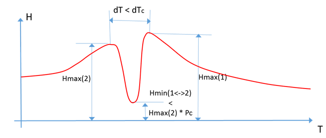
Figure: The two water level (i.e. depth) peaks in the time series are grouped under one event. The higher of the two depths (Hmax(1)) is clearly an extreme event in the current simulation. The other peak (Hmax(2)) is also a candidate for extreme depth event, but evaluation of dTc criterion is negative - this peak occurs too close to the highest peak. Therefore, Hmax(2) is excluded as a separate, independent event and is considered as belonging to the same event leading to the true peak Hmax(1).
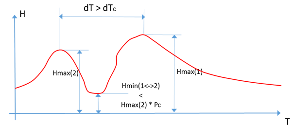
Figure: The two water level (i.e. depth) peaks in the time series are identified as two separate events. The higher of the two peaks (Hmax(1)) is clearly an extreme event in the current simulation. The other peak (Hmax(2)) is also a candidate for extreme depth event. Both criteria are evaluated positively - this peak occurs long time before the highest peak (dT > dTc) and the "bottom" between the two peaks is lower that the specified criterion pc. Therefore, Hmax(2) is also identified as a separate, independent event.
To identify intermittent events and statistics on accumulated variables (e.g. volume, duration, and mass), only the interevent time criterion \(dT_{c}\) applies. Consecutive independent events are separated by time intervals longer than \(dT_{c}\), where the underlying instantaneous variable (e.g. discharge for volume, mass transport for mass) is below the specified threshold (default value for the threshold is zero). E.g. two overflow events (i.e. overflow spills) are considered as independent overflow events if there is zero flow between them for a time longer than \(dT_{c}\).
A threshold value other than zero is relevant for inherently continuous variables, e.g. discharge in pipes: even if the pipe is empty, due to the requirements of the algorithm, a small "numeric" discharge in the pipe will be reported. In order to consider such periods as "dry", the user may want to specify a small discharge threshold other than zero.
This feature is offered via the 'LTS_DISCHARGE_THRESHOLD' parameter in the MIKE 1D engine configuration dialog accessed through the Simulation menu ribbon.
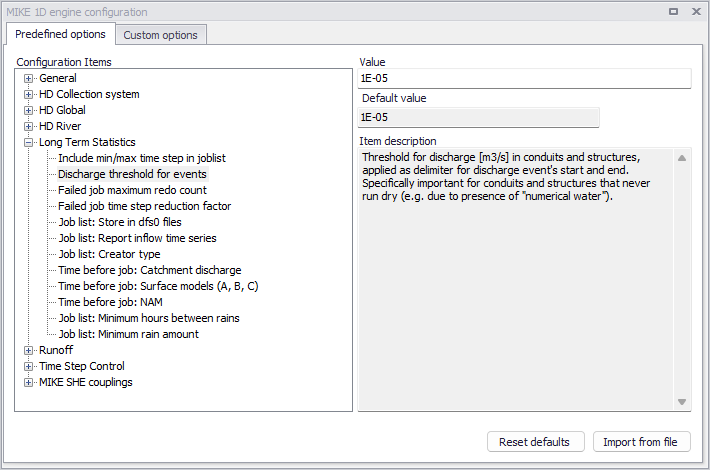
Figure: The MIKE 1D Engine Configuration dialog
Override the Default value of 1E-13 for the parameter by specifying a value in the Value input box.
Examples of identifying independent events are shown in the figure below.
For some statistics parameters, the number of events during a long LTS computation can be very high and the statistics result file size can grow rapidly.
Therefore, the statistical computation can be limited to a specified number of highest events, i.e. only the limited number of most significant events is included into the calculation. This is possible if the purpose of statistical calculation is to focus only on extreme events. In such a case, all insignificant events may be eliminated from the statistics as "irrelevant".
The maximum number of events must be specified within the range 1-5000.
The main parameters which control the event definition for various types of statistics are specified in the LTS Global Parameters editor.
This editor also includes parameters for controlling the LTS outputs:
- Number of events to save: limits the saved results to the specified number of the most significant (i.e. the largest) events
- Discharge and emissions statistics frequency: allows for switching between Monthly and Yearly statistic.
- Continuous DWF TS save frequency: specifies saving frequency for continuous LTS TS outputs for intervals between dynamic simulations.
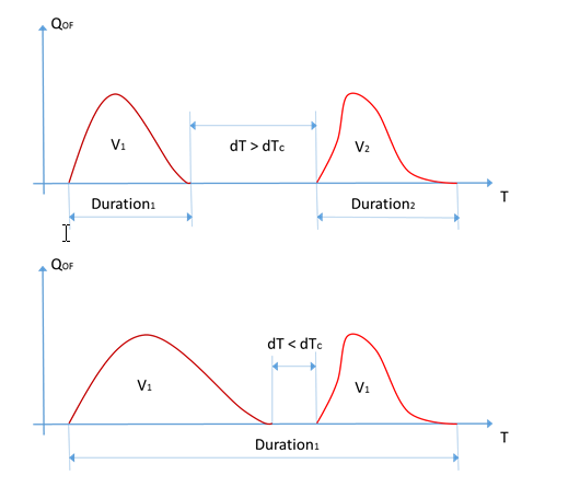
Figure: This example illustrates simulated sewer overflows occurring as two spills separated by a time period with zero flow. In the upper graph, the two spills are separated by dT which is longer than the specified dTc. In this case, MIKE+ LTS considers the two spills as two independent over- flow events and calculates their volumes and durations separately. In the lower graph, the second spill starts shortly after the first one has stopped, i.e. within time interval shorter than dTc. In this case, MIKE+ LTS considers both spills as one overflow event (probably caused by the same meteorological event) and calculates the total volume and duration.
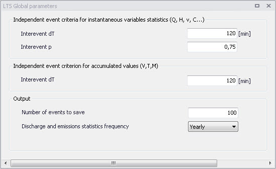
Figure: The LTS Global Parameters editor
| Edit field | Description | Used or required by simulation | Field name in data structure |
|---|---|---|---|
| Interevent dT (For instantaneous variables statistics) | Interevent time criterion or minimum time interval between two peaks to consider them as independent | Yes | Dth |
| Interevent p (For instantaneous variables statistics) | Interevent level criterion or threshold for ration between the lowest mini- mum value between two peaks and the lower peak | Yes | Pc |
| Interevent dT (For accumulated variables statistics) | Interevent time criterion or minimum time interval between two events to consider them as independent | Yes | DtQV |
| Number of events to save | Number of largest events to save in the statistics results (1-5000) | Yes | EventLimit |
| Discharge and emissions statistics frequency | Choice between monthly and yearly chronological statistics | Yes | StatFrequencyNo |
Table: LTS Global Parameters table attributes (Table msm_LTSResult)