Weirs
Weirs, which are essentially low flow barriers across river widths causing changes to flow characteristics, may be modelled for river networks in MIKE+ via the Weirs editor accessed under the River Network setup group.
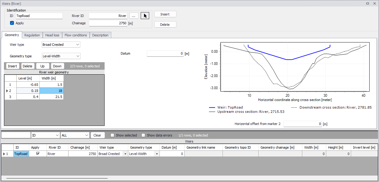
Figure: The Weirs editor accessed through the River Network setup group
Define weirs along river networks in MIKE+ via the main Map setting the Target Layer for feature editing to ‘Weirs.’ See Introduction to structures.
Alternatively, define weir structures via the Weirs editor using the ‘Insert’ button.
Identification
The Identification groupbox holds general information on the weir structures.

ID
Unique string identification for the weir.
River ID
The river branch ID where the weir is located. Use the button with an arrow, to select the location of the structure on the map: this will specify both the River ID and the Chainage of the structure
Chainage
Chainage along the river branch where the weir is located.
Apply
This check box allows the user to toggle the Active status of the weir on and off. The simulations will omit all weirs that are not active.
Geometry
Structure type and geometric properties for weirs are defined in the Geometry tab page of the Weirs editor.
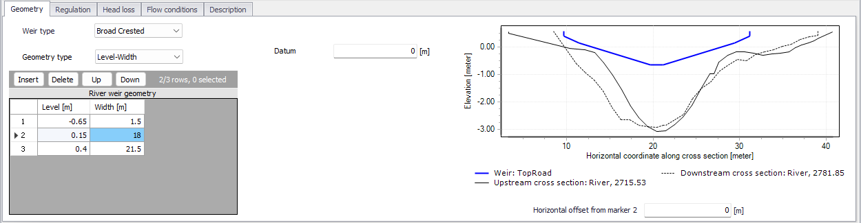
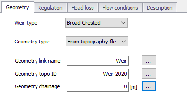
Figure: The Geometry tab on the Weirs editor
Weir Type
The Weir Type defines the type of weir formulation used to calculate flow dynamics over the structure.
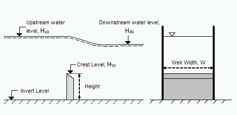
Figure: Weir formula parameters
The weir formulation may be defined as:
- Broad Crested. For Broad Crested weirs a hydrostatic pressure condition is assumed and the Q/h relationship is calculated automatically.
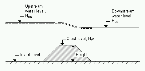
Figure: Broad crested weir
Broad crested weir Geometry Type may be:
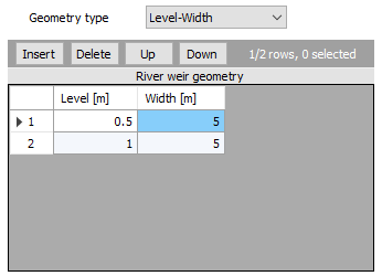
- Level-Width: The weir geometry is defined in a Level/Width table with levels (relative to the datum) and corresponding flow widths.
- The Datum is the vertical offset added to the level column in the level/width table.
- The Level/Width table holds user defined levels and corresponding flow widths. Click on the Insert button to add rows to the table. Note that values in the ‘Level’ column must be increasing.
- From topography file: The weir geometry is specified in the Cross Sections editor. Select the link name (i.e. Branch ID), topo ID, and chainage for the cross section describing the structure geometry.
-
Villemonte Formula. A standard weir expression reduced according to the Villemonte formula is applied. Also see the MIKE 1D Reference Manual for more details. Define the following parameters:
- Width. Width of the flow, W.
- Height. Weir height.
- Invert Level. Bottom datum level.
- Weir Coefficient. Weir coefficient is the multiplication coefficient ‘C’ in the weir formula.
- Weir Exponential Coefficient. Weir exponent coefficient is the exponential coefficient ‘k’ in the weir formula.
The Villemonte formula reads:
(3.3)
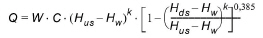
Where Q is discharge through the structure, W is width, C is weir coefficient, k is the weir exponential coefficient, \(H_{us}\) is upstream water level, \(H_{ds}\) is downstream water level and \(H_{w}\) is weir level (i.e. Invert Level + Height).
-
Honma Formula. The Honma weir expression. Also see the MIKE 1D Reference Manual for more details. Define the following parameters:
- Width. Width of the flow, W.
- Crest Level. Weir level, \(H_{w}\).
- Weir Coefficient. The weir coefficient is the multiplication coefficient ‘\(C_{1}\)’ of the Honma weir formula.
The Honma formula reads:
(3.4)
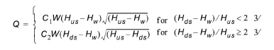
Where Q is the discharge through the structure, W is the width, \(C_{1}\) is the first weir coefficient,
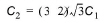 is the second weir coefficient, \(H_{us}\) is the upstream water level, \(H_{ds}\) is the downstream water level, and \(H_{w}\) is weir level
 -
Extended Honma Formula. An extended version of the Honma weir formula is applied. The Extended Honma formula calculates the flow in three flow regimes: 1) Perfect flow, 2) Imperfect flow, and 3) Submerged overflow. The equations reads:
(3.5)
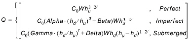
where: -
 - W is weir width
- H is weir height above cross section invert
- \(h_{d}\) is the upstream water level above the crest
- \(h_{u}\) is the down stream water level above the crest
- Provide values for the following parameters:
- Width. Width of the flow, W.
- Height. Weir height, H.
- Crest Level. Weir level.
- Perfect overflow parameters:
- W is weir width
- H is weir height above cross section invert
- \(h_{d}\) is the upstream water level above the crest
- \(h_{u}\) is the down stream water level above the crest
- Provide values for the following parameters:
- Width. Width of the flow, W.
- Height. Weir height, H.
- Crest Level. Weir level.
- Perfect overflow parameters:
\((h_{d}/h_{u})_{i}\) is the depth ratio limit between perfect and imperfect flow regime.
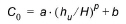
Parameters a, b and p are used to calculate the weir coefficient \(C_{0}\). - Imperfect overflow parameters
Parameters Alpha, Beta and q are used in imperfect overflow calculation - Submerged overflow parameters
\((h_{d}/h_{u})_{s}\) is the depth ratio limit between imperfect and submerged flow regime.
Parameters Gamma, Delta and r used in submerged overflow calculation.
Note on Extended Honma Formula
It is not checked if there is a continuous transition from one flow regime to the next. This has to be ensured by the user through proper selection of the parameters.
Also see the MIKE 1D Reference Manual for more details.
Structure plot
To help ensuring that the geometry of the weir is properly defined, the weir's shape is shown and is compared to its upstream and downstream cross sections. On this plot, the horizontal axis shows the X-coordinates from the upstream cross section. The downstream cross section is then shifted so that its marker 2 is aligned with the marker 2 from the upstream cross section. The weir shape is also centered around this marker 2, but can be moved horizontally using the value 'Horizontal offset from marker 2'.
Note on horizontal offset
This horizontal offset value is only used for the visualization purpose and has no impact on the simulation. Also note that the structure shape is always plotted in a symmetric manner although the actual structure may be asymmetric, and this doesn't affect the simulation neither as long as the flow area in the structure is correct.
Note on weir's flow area
Since a weir is a structure causing a contraction loss and subsequently an expansion loss, the geometry of the weir must be such that the cross sectional area at the weir is less than the cross sectional area at both the upstream and the downstream cross sections for all water levels.
Regulation
Flow regulation setting may be defined for river network weirs via the Regulation tab page of the Weirs editor.
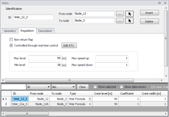
Figure: The Regulation tab on the Weirs editor
Non Return Flap
Activate the ‘Non return flap’ option to control the direction of flow over weirs:
- Only Positive Flow: Only positive flow is allowed, i.e. whenever the water level downstream is higher than upstream, the flow through the structure will be zero.
- Only Negative Flow: Only negative flow is allowed, i.e. whenever the water level upstream is higher than downstream the flow through the structure will be zero.
- No Flow: The flow through structures will always be zero regardless of upstream and downstream water levels.
Apply flow factor
When this option is active, the discharge computed through the weir is multiplied by a flow factor. This factor's value is specified in the Flow factor field. The factor is a dimensionless factor, and a value of 1 means that no change is applied to the computed discharge. A value lower than 1 can typically be used to describe the reduction of the flow through the structure due to obstacles, like debris, restricting the flow area in the structure.
Head Loss
For broad crested weirs, parameters for computing energy loss through the structure may be defined via the Head Loss tab page.
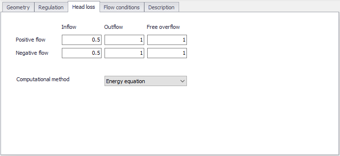
Figure: The Heal Loss tab for broad crested weirs
Head loss factors may be defined depending on flow direction across the weir (positive or negative flow direction).
Besides, a computational method must be selected. Two options are available:
- Energy equation: with this method, the flow through the structure is solved using the energy equation, in order to compute the discharge in the structure as a function of the head loss factors. The computed discharge is then applied at the calculation point. This is the preferred option in case there are big changes in cross sections before and after the structure, or if the flow area of the structure is much less than that of the river.
- Shallow water equation: with this method, the flow through the structure is solved adding a head loss term to the shallow water equation (Saint-Venant momentum equation), this term being a function of the head loss factors. With this method, the same equation is applied at structures' locations as at other regular calculation points (without structures). This ensures a continuity of the results between the upstream / downstream reaches and the structure, e.g. also including a bed friction between the upstream and downstream cross sections of the structure. Additionally, this method also enforces the use of velocity in upstream and downstream cross sections to compute the head loss, instead of using the velocity in the structure. This option is mainly designed for scenarios where the structure creates little or no head loss for low water levels, as e.g. for an overarching bridge. See the "Head loss mode" in the MIKE 1D reference manual, for more information.
Note
When the flow through the structure becomes supercritical, the applied method is always the Energy equation. Besides, the 'Shallow water equation' method cannot be applied for structures located on rivers of type 'Structure link'. When several structures exist at the same location, if any of them uses the Shallow water equation method, then all other structures at the same location will also apply the same equation no matter the selected method in their properties.
Flow Conditions
For broad crested weirs, a tab for Flow Conditions is available. Free overflow Q/h relations are calculated automatically by clicking on the ‘Calculate Q/h relations’ button once the ‘No. of Q/h relations’ value has been specified.
Allow for Recalculation
Q/h relations can either be calculated automatically or entered/edited manually. If the Q/h relations have been modified manually it is possible to lock the values by disabling the ‘Allow for recalculation’ option. This will ensure that Q/h relations for this structure are not recalculated.
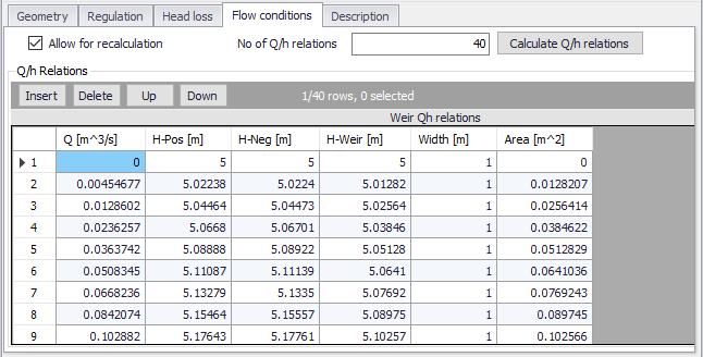
Figure: The Flow Conditions tab for broad crested weirs
The results of the Q/H relations calculations are shown in the Q/h Relations table and includes values for:
- Q: Structure discharge
- H-Pos: Level upstream in case of positive flow
- H-Neg: Level downstream in case of negative flow
- H-Weir: Level at structure
- Width: Structure width for actual structure level
- Area: Structure area for actual structure level
To compute Q/h relation values, the nearest upstream and downstream cross sections are used. The cross sections must be located within a distance which is smaller than the user-defined maximum grid-spacing (‘Max dx’) for the river branch in question. The Q/h relations cannot be calculated unless cross sections are defined.
Note
Note that Q/h relations must be re-calculated if changes are made to the weir and/or up/downstream cross sections. This is done using the ‘Calculate Q/h relations’ button for an individual structure or using the ‘Recalculate flow conditions’ tool in the ‘River Network’ menu ribbon.
Description
Use the Description tab to add free text descriptions for weirs. It offers options for providing asset and model management information, as well as attributes for quick model data query.
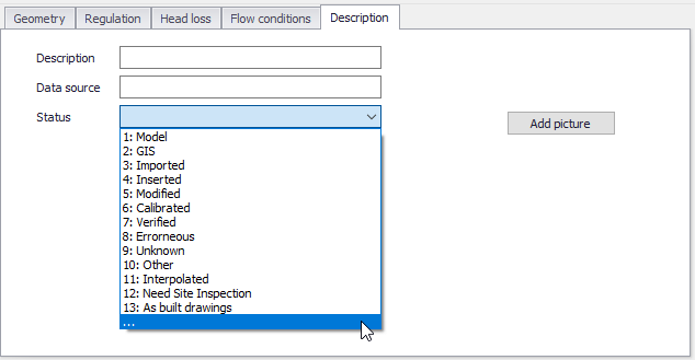
Figure: The Description tab on the Weirs editor
- Description: Free text description for the weir structure.
- Data source: Free text describing data source for the weir data.
- Status: Project-defined status information that may be used for model build management or e.g. model data query. Pre-defined codes are contained in the Status Code editor which may be accessed via the ellipsis button from the Status dropdown menu.
- Add picture: Option for adding images associated with the weir structure.