Junctions
A crucial element of the water distribution network is the junction nodes, that define the interconnection between the pipes that make up the network. Junction nodes are also placed at points of water consumption or inflow, at points where specific analysis values (e.g., pressure, concentration, etc.) are desired, and at any points where pipe attributes (e.g. diameter, roughness, etc.) change.
Junction nodes are either defined graphically in the Map window using the Drawing tool in the Edit tab with Junctions selected as the Layer to edit, or by manual data entry using the Junction Editor dialog box.
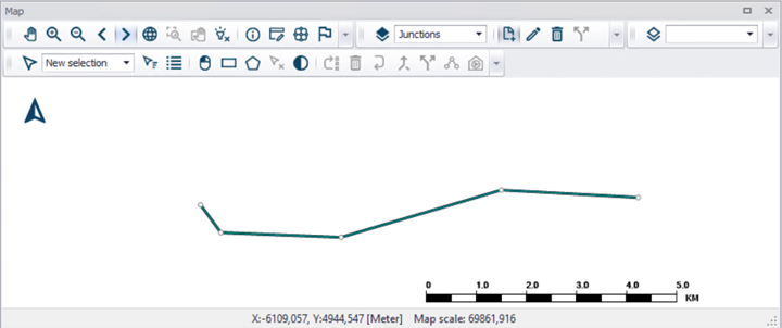
Figure: Draw Junctions
The Junction editor allows to define the junction’s ID, location, any external demand, initial water quality conditions and a description. The Junction Editor dialog box is reached by expanding Network Elements and selecting Junctions.
Geometry
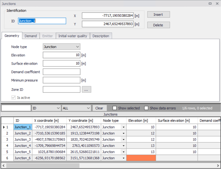
Figure: Junction Editor, Geometry tab
'Insert' button creates a new Junction. 'Delete' button removes the selected Junction.
ID
This data entry is used to specify an ID which uniquely identifies the junction node. The junction ID acts as a unique look up key that identifies the node from all other nodes. A node can be a junction, reservoir, or tank. Therefore, no two nodes may have the same ID. However, a node and a link (i.e., pipe, pump, or valve) can have the same ID. The node ID value can be any string value (up to 40 characters).
Coordinates
The X and Y data entries are used to define the physical (map) location of the junction node. When defining the junction nodes graphically on the Map window using the Draw tool, the X, Y location is automatically entered.
Node type
Two types of Junctions are available:
- Junction
- Emitter
Junction is used to describe normal water junctions. An emitter can be used to describe a pressure dependent discharge at the node and is described in the chapter below.
Elevation
This data entry defines the elevation above a common datum for the junction node. This value is used to determine the difference in pressure and pressure head at the node during a simulation. The default elevation is zero. Junction nodes should have their elevation specified so that pressure computations can be carried out.
Surface elevation
This data entry defines the surface elevation above a common datum for the junction node, in units of ft. or m. This value is only used to display the surface elevation in the Longitudinal Profile Plot.
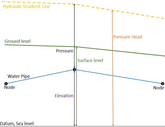
Figure: The difference in Elevation and Surface level
Minimum pressure
This data entry defines the estate height above the junction node elevation. This data entry is used to calculate Tap Pressure at the junction node and is used to verify the minimal pressure at the node.
Demand coefficient
Demand coefficient allows you to define the share from the whole network demand, which is taken by the node. This field is used only by the Demand Distribution function.
The demand distributed to a node is calculated as
(3.1) 
where:
qi = node demand
Qt = total network demand
Ct = sum of all demand coefficients
ci = node demand coefficient
Any node where the demand coefficient is not defined will get no demand from the total network demand.
Zone ID
This is an optional name for the zone to which the junction belongs. When a zone ID is specified, this zone will be listed in the 'Zones' editor. The '…' button can be used to select an existing zone.
Is active
This check box controls whether the junction will be included (when ticked) or omitted (when unticked) in the simulations. The junction is automatically omitted as soon as all connected links are also set to inactive.
Demand
The Demand tab is used to view, add or edit demands for a specified Junction. Note that all Demands in the model are stored and can be edited in the Water Demand | Multiple Demand table.
The listed demands in this tab are the items in Multiple Demands with the current Junction as “JunctionID”. The list of demands is updated if another junction is selected in the lower grid.
Junctions may have zero or any number of demands assigned to them. It is also possible to assign separate patterns to the demands assigned to a given junction.
The demand is specified as a constant. If flow is leaving the network system at this junction node, then a positive value should be specified. If an inflow into the network system occurs at this junction node then a negative value should be specified.
The amount of water leaving (or entering) the model in a specific timestep in an extended period simulation will be the junction demand value multiplied by a factor. These factor are stored in time series called patterns and assigned with a Demand pattern ID, see Tables > Patterns.
A demand for a larger part of the system can also be computed by globally defining the demand for the entire network (or a selected part of it) and then having MIKE+ distribute this demand to each of the network nodes using the Distributed Demand dialogue box. See Tools | Distributed Demand.
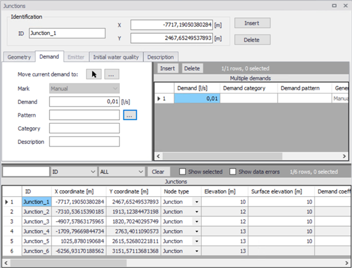
Figure: Junction editor, Demand tab
A new demand is created by clicking Insert by the list of demands in the right window.
The demand editor in the left window shows the properties of the selected demand.
Demand
The demand, specified as the flow leaving (or entering if the value is negative) in this junction.
Demand Pattern
This data entry allows you to define the ID of the demand pattern to be applied to the junction node demand values during an extended period simulation. The factor in this demand pattern will be multiplied to the defined Demand.
Demand Category
This data entry allows you to enter a description identifying the demand being entered. The demand category can be used when using the Distributed Demand tool.
Description
This data entry allows you to enter a description identifying the demand being entered.
Move Current Demand to
This allows the user to move a single Demand from the active Junction to another Junction. Either by selection from a list of Junction ID or by selecting a Junction in the map. The moved Demand will be removed from this Junction and placed at the new Junction.
Mark
Each Demand is given a Mark based on how it was created.
- Manual
- Distributed Demand
- Demand Allocation.
Demands created in the Junction Editor are marked “Manual”.
Emitter
This tab contains parameters of an emitter located at the junction node. A junction is treated as an emitter if the Node Type is set to Emitter in the Geometry tab. Emitters are needed to model flow through sprinkler systems and irrigation networks. They can also be used to simulate leakage in a pipe connected to the junction if a discharge coefficient for the leading crack or joint can be estimated.
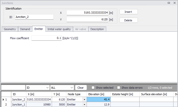
Figure: Emitter tab
Flow Coefficient
This data entry allows you to define the flow coefficient of the emitter. Flow out of the emitter equals the product of the flow coefficient and the junction pressure raised to a power.
Initial Water Quality
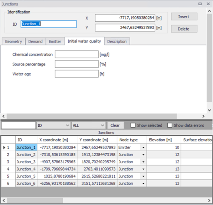
Figure: Junction editor, Initial water quality tab
The initial water quality at the start of a simulation can be assigned to individual nodes or to groups of nodes. The initial water quality can represent one of the following, depending on the type of water quality simulation.
Concentration
Initial concentration for chemical constituents in a Chemical propagation analysis.
Percentage
Initial percentage of water originating at a specified source node for Source tracing simulation.
Hour
Initial age for Water age determination.
These Initial water quality values will only be used when a Water Quality simulation of the corresponding type is started.
By default, all nodes are assigned with an initial water quality of zero.
Description
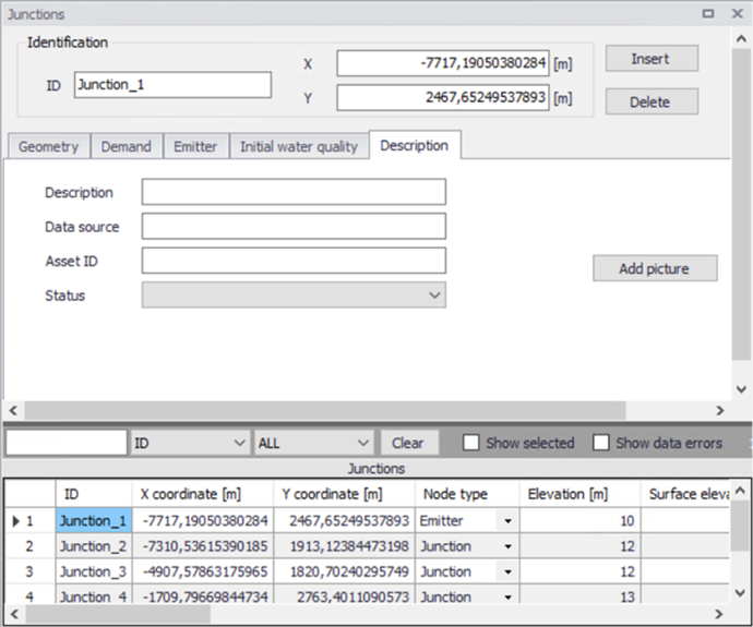
Figure: Junction editor, Description tab
Description
This data entry allows you to enter a description for the selected junction.
Add picture
The 'Add picture' button allows to add photo for individual pump. Once loaded from external source, the picture will be displayed on this tab.
Data source
This data entry is used to specify a corresponding asset data source, which identifies the Junction (such as database table or a database file name) in the asset management system.
Status
This drop down selection list data entry allows you to define whether the Junction is imported (i.e existing node was imported from the external data source), or is inserted, modified, GIS, calibrated or similar. By default, the status is undefined.
Asset ID
This data entry is used to specify a corresponding asset ID, which uniquely identifies the junction node in the asset management system (such as GIS, for example).
Attributes
Attributes from the database are summarized in the table below.
| Field | Database name | Description | Mandatory? | Default value |
|---|---|---|---|---|
| ID | MUID | Identifier, must be unique for all node types including Tanks etc | Yes | Labels are generated in sequential order |
| Node type | TypeNo | Type of node | Yes | Junction |
| Elevation | Elev | Elevation from datum | Yes | 0 |
| Surface elevation | Z | Surface elevation from datum at this position | No | 0 |
| Demand coefficient | DemCoeff | Coefficient for calculation of Distributed demand | No | 0 |
| Minimum pressure | MinPre | Estate hight over node elevation. | No | |
| Flow coefficient | Em_FlowCoeff | Flow coefficient of emitter | Yes, if Node type = Emitter | |
| Chemical concentration | Init_Quality_Concentration | Initial concentration for Chemical concentration simulation | No | 0 |
| Source percentage | Init_Quality_Percentage | Initial percentage from specified source in Source tracing simulation | No | 0 |
| Water age | Init_Quality_Hour | Initial age in water age simulation | No | 0 |
| Description | Description | Descriptive text | No | |
| Data source | DataSource | Source of data | No | |
| Asset ID | AssetName | ID in asset source | No | |
| Status | Element_S | Status or origin of data | No |
Table: Junction attributes