Catchment Processing Tool
The catchment processing tool is an automated and reproducible way to calculate:
- imperviousness, time of concentration and other hydrological parameters for Time-Area runoff models
- distribution of land uses, for Time-Area, Kinematic Wave, Linear Reservoir or New UK / Wallingford runoff models
- imperviousness and catchment width for SWMM hydrological models.
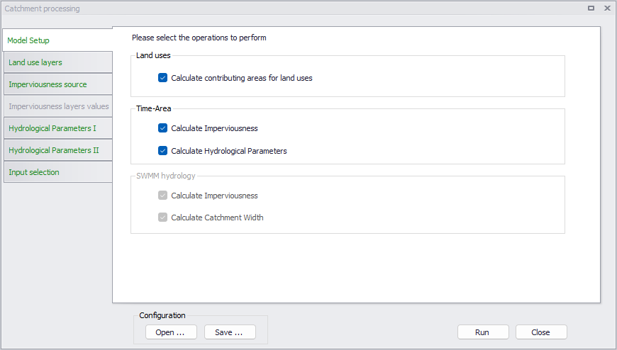
Figure: The start-up dialog of the catchment processing wizard
Model setup
The first step in the catchment processing is selection of which parameters to calculate. For 'Rivers, collection system and overland flows' projects, the tool can calculate the contributing areas of land uses on each catchment, when catchments are set to work with land uses definition. For 'Time-Area' models specifically, the tool can additionally be used for calculation of hydrological parameters.
For SWMM model setups, the tool can be used for performing the following operations for SWMM hydrological models:
- Calculate Imperviousness. Use the tool to derive or set imperviousness values for catchment .
- Calculate Catchment Width. Catchment width for SWMM catchments is computed as Area / MaxLength, where MaxLength is:
- If the catchment is connected to a node, this is the distance from the connected node to the farthest point in the catchment.
- If the catchment is connected to another catchment, the length is the maximum length across the catchment between two opposite points along the border.
Calculating only catchment width using the tool requires no further steps after selection of the option from the 'Model Setup' tab.
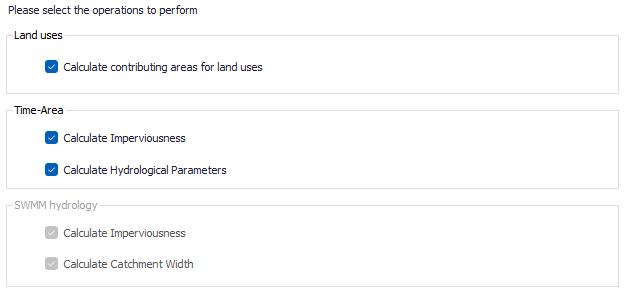
Figure: Selection of parameters to calculate
Land use layers
The 'Land use layers ' tab is active when the tool is used for calculating the contributing areas for land uses. This function can be applied to catchments with hydrological model Time-Area, Kinematic Wave or Linear Reservoir when their option 'Use land use distribution' is ticked, or New UK / Wallingford. This option is meant to compare the extents of land use polygons and catchment polygons, and:
- Define the list of land uses covering each catchment
- Estimate the percentage of coverage of each land use.
Land use polygons must be defined in a polygon feature layer loaded on the map prior to using the tool. Two formats are supported for the definition of the various land use layers:
- Either each land use is defined with its own feature layer (e.g. shape file), i.e. all polygons in a given layer will be assumed to describe the same land use
- Or multiple land use types can be defined in the same feature layer, with an attribute of the layer being used to identify the land use type for each polygon.
In this tab, all valid existing land uses defined in the project are listed, and the table is used to select which land uses to process and associate them with polygon layers added to the map. Land uses defined for the 'New UK / Wallingford' model and using the 'New UK' runoff volume type are excluded from the table, because this type of land use is to be defined for the remainder of the catchment not covered by any land use with the 'Fixed coefficient' runoff volume type.
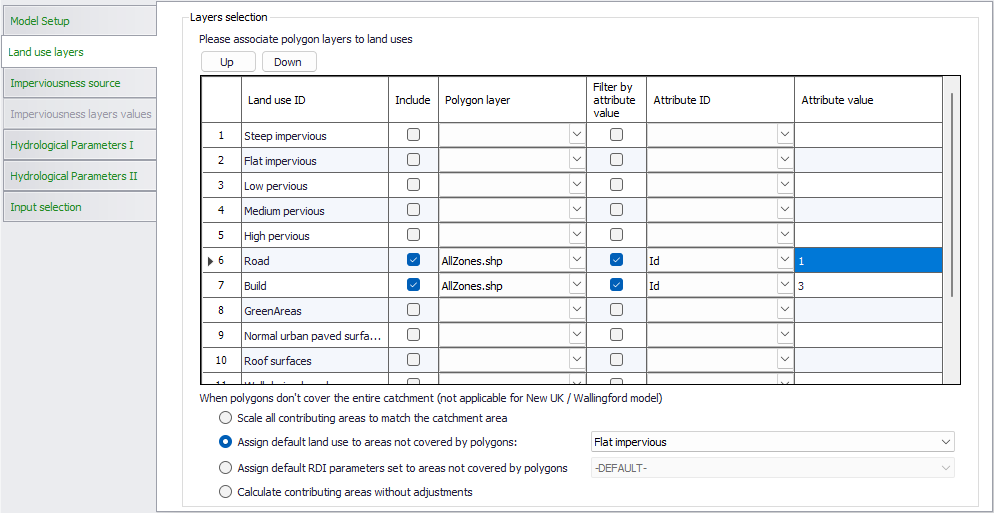
Figure: Polygon layer selection for calculation of land use distribution
The following settings are controlled in the table:
- Land use ID: this column lists all valid land uses defined in the project, in the 'Land uses' editor, and all RDI parameter sets, defined in the 'Parameters RDI' editor.
- Include: this check box controls which land uses (including RDI parameters) are being processed by the tool. Land uses which are not included will be ignored by the tool and won't be assigned to catchments.
- Polygon layer: this column is used to select the polygon layer to associate with land uses included in the operation. The drop-down list shows all available polygon layers (shape files or feature classes from geodatabases).
- Filter by attribute value: when this is unticked, all polygons within the selected polygon layer will be associated with the corresponding land use. When it is ticked, an attribute from the polygon layer will be used as a filter, and only the polygon for which the attribute matches a user-defined value will be associated with the corresponding land use.
- Attribute ID: When 'Filter by attribute value' is ticked, this list shows all attributes available in the selected polygon layer, and is used to select the attribute which will be used for the filter.
- Attribute value: When 'Filter by attribute value' is ticked, this is the value that the selected attribute must have for polygons to be associated with the corresponding land use.
Note
The order of the layers is important. If some of the polygons overlap, only the uppermost layer (i.e. higher on the list) is considered in the overlapping area.
Unless the catchments are fully covered by the polygon layers, there may be parts of the catchment which are not covered by any of the land uses. The radio buttons at the bottom are used to control how these remaining areas are processed. The available options are:
- Scale all contributing areas to match the catchment area: for each catchment individually, the contributing percentage of each land use is multiplied by a correction factor such that the sum of all land use contributing percentages matches 100% for the catchment. This method is usually to be used when the fraction of the catchment not covered by any polygon layer is small (e.g. when the catchment is supposed to be fully covered by polygons but some uncovered areas exist due to inaccuracies in the polygons digitization).
- Assign default land use to areas not covered by polygons: for this option, select the default land use to apply, from the drop-down list. This option allows to provide polygons only for some land uses (e.g. impervious areas like buildings and roads), and associate the rest to a default land use (e.g. natural areas).
- Assign default RDI parameters set to areas not covered by polygons: this option is to be used for catchments combining either 'Time-Area + RDI', 'Kinematic wave + RDI', 'Linear reservoir C1 + RDI' or 'Linear reservoir C2 + RDI'. With this method, all parts of the catchment not covered by any polygon will be associated with the RDI hydrological model and with the selected parameters set.
- Calculate contributing areas without adjustments: this method keeps the computed land use contributing areas unchanged. If some parts of the catchment are not covered by any polygon, it will usually result in having these areas not contributing to runoff on the catchment.
These radio buttons are only applicable for rainfall-runoff models Time-Area, Kinematic Wave and Linear Reservoir. For New UK / Wallingford models, the part of the catchment not covered by any polygon will be applied the single land use with the 'New UK' runoff volume type, which is selected in the catchment.
Imperviousness source
The 'Imperviousness source' tab is active when the tool is used for deriving or setting catchment imperviousness values.
The second step in the calculation of imperviousness is specification of the source of imperviousness values during processing.
Imperviousness for MIKE+ catchments can be calculated as a constant value or as a weighted average of imperviousness of multiple polygon layers. The layers should be pre-loaded in the project to be selectable in the wizard.
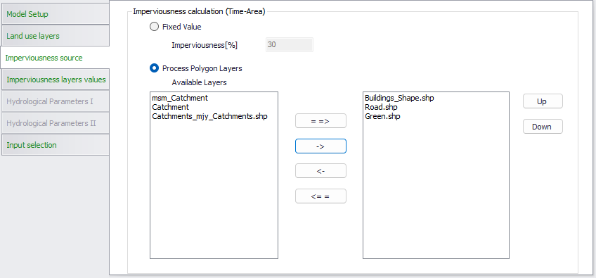
Figure: Polygon layer selection for calculation of imperviousness
Imperviousness layers values
The next step in the calculation of imperviousness is specification of the imperviousness for each selected layer. Please note that the order of the layers is important. If some of the polygons are overlapping, the value from the uppermost overlapping layer (i.e. higher on the list) is prioritized.
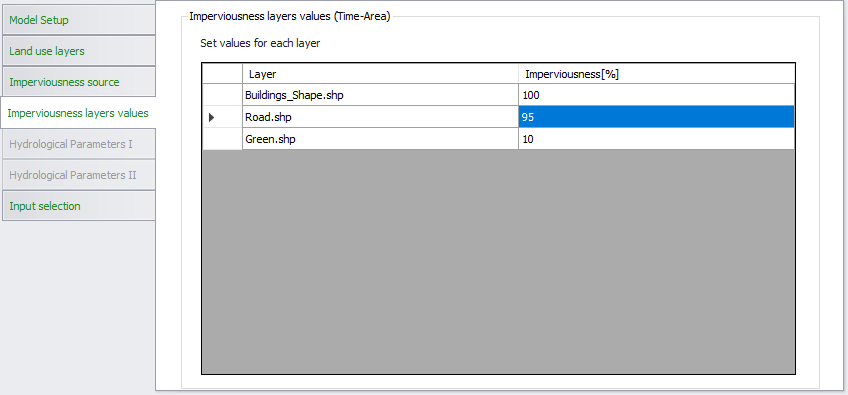
Figure: Specification of parameters for calculation of imperviousness
During the computation, areas of the catchments not covered by any layer will be assumed to be highly pervious (imperviousness = 0%).
Hydrological parameters
Several hydrological parameters for MIKE+ Time-Area runoff models can be calculated. The configuration is split in two tabs, with the principles explained in the dialogs.
Note
Catchments must be connected to the pipe network in order to compute these parameters, as the connection is required for the computation of time of concentration.
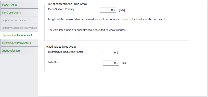
Figure: Specification of the first set of hydrological parameters for Time-Area runoff models
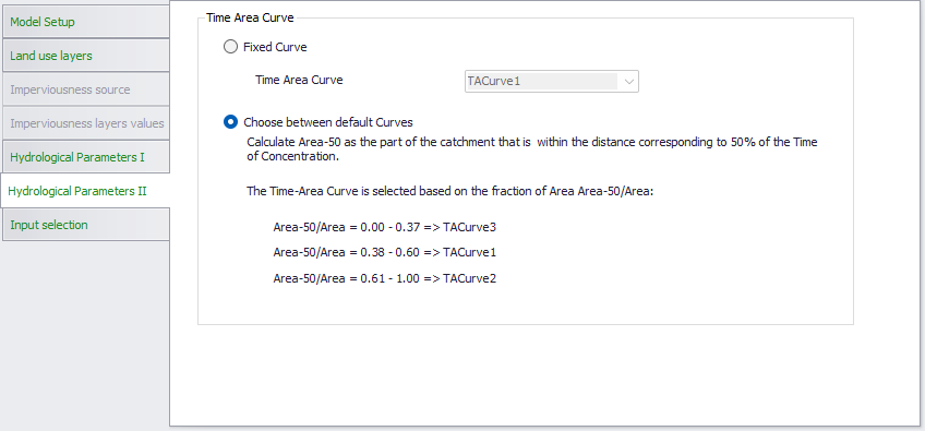
Figure: Specification of the second set of hydrological parameters for Time-Area runoff models
Input selection
From this tab, two options are available to control which catchments will be processed by the tool:
- All catchments: land use distribution will be computed for all catchments in the project
- Catchments from selection on the map: only the catchments selected when the tool is executed will be processed.
Running the tool
The final step is to execute the tool using the ‘Run’ button at the bottom of the window.
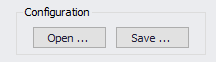
Configuration
A section for saving or loading a Catchment Processing configuration *.xml file. Use the Save button to save the current processing configuration into an *.xml file. The Open button loads a previously-saved *.xml configuration file.