2D Overland Menu
The 2D overland menu offers tools and functionalities related to creating and editing the 2D domain, 2D structures, or other 2D input data like spatial variations of surface roughness.

Undo/Redo
![]()
Offers Undo or Redo options during data editing.
Edit Features
The Edit Features Toolbox contains tools that are used for interactively laying out the 2D overland model on the Map. The list of tools within the toolbox are listed below.
Boundary type
This list is active only when the selected target layer is '2D boundary conditions'. The boundary type controls the type of boundary to be drawn on the map:
- For the point source type, the boundary conditions are represented by points on the map, which are located within the 2D domain.
- For the distributed source type, the boundary conditions are represented by polygons on the map, which are located within the 2D domain.
- For the other types, boundary conditions are represented by polylines along the borders of the 2D domain.
![]()
Create
This tool is used graphically add a component by selecting the target layer and clicking within the Map view. Double click to end the feature creation.
![]()
Edit
For editing features i.e. moving nodes, realigning polyline features, or reshaping polygons. Right click outside the feature being edited to end the editing.
![]()
Delete
Deletes the selected features.
![]()
Split
This tool is used to graphically split polygons on the Map (e.g. for 2D initial conditions or 2D surface roughness polygons).
![]()
Import shape
This tool is used to import mesh arcs from a shape file.
![]()
Open layer editor
Offers quick access to the Editor of the model feature selected from the Map. The editor is opened as a new tab document on the main window.
Selection
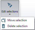
The 'Edit selections' list contains tools for editing/manipulating selected elements:
- Move selection
- Delete selection
2D domain tools
This group contains tools that are used to create and edit the 2D domain.
![]()
Generate grid/mesh
When the 2D domain file is defined with the source type 'Domain file created from MIKE+ definition' in the '2D domain' editor, this button generates the grid or the mesh according to the grid and mesh definitions shown on the map. It is the same functionality as for the 'Generate grid' or 'Generate mesh' buttons in the '2D domain' editor.
![]()
Delete grid/mesh
When the 2D domain file is defined with the source type 'Domain file created from MIKE+ definition' in the '2D domain' editor, this button clears the 2D domain.
![]()
Start interpolation
When the 2D domain file is defined with the source type 'Domain file created from MIKE+ definition' in the '2D domain' editor, this button starts the interpolation of input elevation data on the 2D domain.
![]()
2D cross section plot
This opens a tool to draw cross sections from the 2D domain (possibly combined with river cross sections) and/or from a DEM.
Cross section plots are created from the main Map view, and the input files must therefore be loaded beforehand. From the 'Add cross section plot' window, it is possible to control the following:
- 2D domain and river cross sections: when this option is selected, the cross section of the 2D domain file will be shown for the selected location. This cross section can optionally include a river cross section, for coupled models.
- DEM layer: when this option is selected, the cross section of the selected DEM will be shown for the selected location.
- Maximum spacing between points: this controls the number of points to be plotted along the 2D cross sections. A different spacing can be specified for the 2D domain and for the DEM, in order to adapt to their respective resolutions.
Two types of locations can be used:
- Digitize location on map: when this option is selected, the location of the cross section is digitized on the map using a polyline. Double-click to stop digitizing and to show the cross section plot. While digitizing the polyline, it is possible to include a river cross section to obtain a common cross section plot of the coupled model, based on 1D and 2D input data: to do so, simply click at the intersection between the river and the cross section during the digitization process.
- Load from file: if the location of a previous cross section plot has been saved to a file, this location can be re-used by selecting this file, in order to create a new plot from the same location.
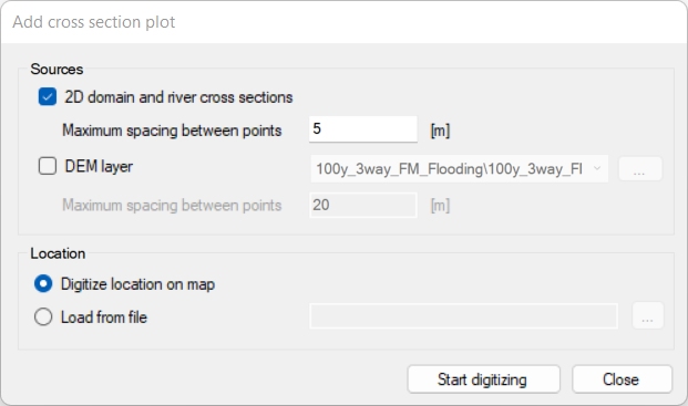
Figure: The tool used to create Cross section plots of 2D data
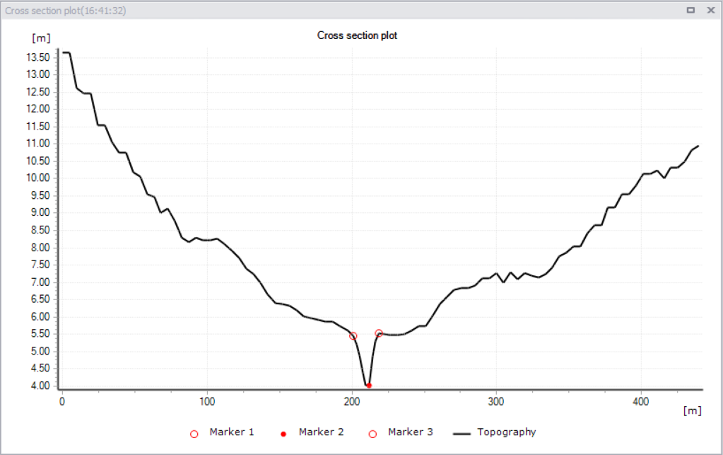
Figure: The Cross section plot window showing a combined river and 2D overland cross section
The context menu of the cross section plot offers the following options:
- Zoom to full extent, Zoom in, Next zoon, Previous zoom: Allows to zoom in and out on the plot. Zoom to full extent brings you back to the full view of visible cross section data on the plot. Panning is also enabled upon activation of zoom options, using the 'Shift' key.
- Copy to clipboard: Copies the cross section view displayed to the clipboard and allows it to be pasted into other applications.
- Save to image file: Saves the cross section view displayed to an image file on the disk, using various supported image formats.
- Export to text file: Saves the cross section's data to text file, to further process the obtained elevation data.
- Save location: Saves the location to a file, to later create new cross sections at the same location.
- Print: Prints the cross section view displayed to the clipboard.
- Properties: Activate this option to view the Cross section plot Properties dialog.
Note
Closed river cross sections cannot be combined to the 2D domain's topography. They will be ignored if they are selected during the digitization of the cross section location.
![]()
Exclude rivers
This opens a tool which generates mesh arcs, defining polygons representing the river extent and being excluded from the mesh. When the 2D domain is defined with a rectangular grid, the tool creates polygons defining inactive areas. This is to be used when the 2D domain file is defined with the source type 'Domain file created from MIKE+ definition' in the '2D domain' editor, in order to ensure that the river extent is not modelled both in the 1D river network and in the 2D overland domain.

Figure: The tool used to exclude river extents from the 2D overland domain
A number of selection methods are available for defining channels to be excluded:
- All channels: Creates polygons describing the area covered by all natural channels (specified in the CS network Pipes and Canals editor) or rivers (specified in River network Rivers).
- Channels from selection on the map: Select channels via the Map or network feature overview tables. The currently active selections will be excluded from the 2D domain.
- Channels inside polygons from map layer: Select channels to be excluded from a layer only (for example a catchment) defined by a polygon. This polygon feature must be part of the model (msm_Catchment) or loaded into the model as a background layer to be selected.
- Channels from table: Click on the 'Edit table' button to import individual or all natural channels (specified in CS network Pipes and canals) or river branches (specified in River network | Rivers) and tick on/off the channels to be excluded. Alternatively import a list of channels in text format via the 'Import from file' option. The text file must contain three columns with the upstream chainage value, the downstream chainage, and the channel ID. The columns should be space-delimited and provided in this order.
- Single channel: Only exclude one channel. In this case, select the ID of the channel to be excluded as well as which section of the channel to exclude (upstream and downstream chainage of the channel).
The polygons encapsulating the selected channels, and to be excluded from the 2D domain, are defined based on the extents of cross sections along channels. Two methods can be used:
- Use cross-sections and channel alignment: The location of the polygon's border is based on the extent of the cross sections in the river reach, as well as on the direction of the channel. A vertex is added to this border at each cross section location, and at each change of direction (i.e. at each vertex) of channel. This method ensures that the polygon's border follows the channel's direction between cross sections, which is convenient when the distance between cross sections is long compared to the channel's width.
- Ignore channel alignment when distance between cross sections is less than a specified distance: The location of the polygon's border is solely based on the extent of the cross sections in the river reach. The polygon's border has a straight shape between two consecutive cross sections. This method is convenient when the distance between cross sections is small compared to the channel's width, as the number of cross sections is sufficient to correctly define the bank's location.
It is recommended to use the same method as the one used to create the 1D-2D couplings, in case they have been created with the 'Create couplings' tool, to ensure consistency between the borders of the 2D domain and the coupling locations.
By default, the generated polygons will be limited by the extent of the existing 2D domain. This will e.g. avoid creating arcs for a flexible mesh creation, outside of the expected area. This limitation can however be removed by activating the option 'Extend polygons beyond 2D domain's borders'.
After running the tool to generate the polygons describing the excluded river extents, the 2D domain must be regenerated to take these polygons into account.