Curb Inlets
The connections between pipe systems and overland flow networks to simulate the capture capacity (and surcharge) of side inlet pits and grates can be approximated in MIKE 1D using a combination of orifices and weir geometry. However, a method has been developed to incorporate the geometry of the inlet structure (Curb Inlet) via a network element which allows user input of the empirical relationship governing the structure capacity.
A typical Curb Inlet/grate configuration is shown below. Flow into the pit chamber is via both a grate and side weir (operates as an orifice for deeper flow depths).
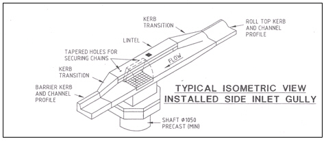
Figure: A typical curb inlet configuration
Standard curves have been developed in Australia for "ON-GRADE" type (using a \(Q_{approach}/Q_{capture}\) relationship where flow can bypass the structure) and "SAG" type (using a Depth/Q relationship at locations/low points where water collects). However the formulation with MIKE 1D allows for non-specific and user defined relationships. An example of the empirical curves developed for the ON-GRADE type is shown below, with the flow captured represented as a proportion of the approach flow, and varying with approach slope.
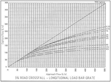
Figure: Example of empirical curves for On-Grade type
A Curb Inlet (Lintel) is a connection between two nodes of a MIKE 1D urban network (two-directional flow and submerged flow possible), describing the transfer of flow at a grate or inlet from an overland flow network to the sub-surface pipe network. The Curb Inlet dialog is accessed via the “TOC | Network | Curb Inlets” menu.
There are two types of Curb Inlet:
- SAG Type, where the connection node on the overland flow network is located at a sag or low point where water will collect. Transfer capacity of the connection is specified as a DQ-relation (tabular data type).
- ON-GRADE Type, where flow in the overland flow network can continue past the connection node. Transfer capacity of the connection is dependent on the slope of the overland flow network, and specified as a Capture ID (collective of QQ-relations defining the capture rate as a proportion of approach flow).
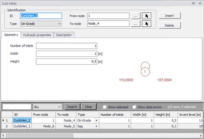
Figure: The Curb Inlet data dialog
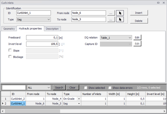
Figure: The Curb Inlet Hydraulic Parameters data
User defined parameters in the Curb Inlet dialog include:
- Invert level (m) defining the point at which spilling starts (similar to weir crest level). The user is shown a system calculated invert level which is the same as the invert of the connection node in the overland flow network. As with weir flow, a crest level at least 0.01 m higher than the connection node invert level is recommended for initial condition stability.
- Freeboard (m), defining a critical water level (Ground level - Freeboard) at the connection node in the pipe network below which the defined DQ and QQ-relations apply. For submerged and reverse flow (surcharge), the transfer capacity of the connection reverts to a standard orifice relationship.
- Slope (%), representing the slope of the steepest link in the overland flow network entering the connection node (only applies to ON-GRADE Type). The system calculated slope is used in the calculation unless a user defined slope is specified.
- Blockage factor (%) which can be used to account for debris blockage at the grate/inlet. This linear factor is applied to the tabular data sets defining the transfer capacity of the connection.
- Number of Curb Inlets, allowing multiple curb inlets of the same specified geometry (transfer capacity) applied at the same location within a single connection.
- Default rectangular orifice geometry, applies to those flow cases (submerged and reverse flow) were the defined DQ and QQ-relations do not apply. This generally applies when water levels at the connection node in the pipe network exceed the critical level defined by the Freeboard, including reverse flow (surcharge).
There are no limitations on the number of curb inlets specified at one location; however, the connectivity must be ‘From’ a node in the overland flow network ‘To’ a node in the pipe network, for correct automatic calculation of slope. Note: Link slopes must be calculated in the link dialog for automatic calculation of slope to operate.
The On-grade Capture dialog allows the user to group together QQ-relations (tabular data) that comprise a single On-grade Curb Inlet geometry (similar in function to the Topography dialog). As the transfer capacity for an On-grade Curb Inlet is dependent on the slope in the overland flow network, a number of QQ-relations can apply.
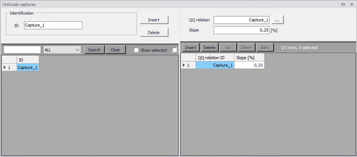
Figure: The On-Grade Capture data dialog (On-Grade Type)
For calculated or user defined slopes in the Curb Inlet dialog that are outside the range of slopes specified in the On-grade Capture dialog, the closest slope curve will be used. For intermediate calculated or user defined slopes (lying between slope curves in the On-grade Capture dialog), linear interpolation is applied.
In the case of an On-grade Curb Inlet capacity that is not dependent on slope of the overland flow network, the user needs to define the On-grade Capture with a single QQ-relation. Note: In this case, the calculated or user defined slope in the Curb Inlet dialog for ON-GRADE Type will be ignored.
Capacity curves
Two curve types specified in the tabular data (Curves & Relations) can be used with the two different types of Curb Inlets.
- Capacity Curve, DQ (depth/discharge relation specified in the Curb Inlets dialog)
- Capacity Curve, QQ (\(Q_{approach}/Q_{capture}\) relation specified in the On-grade capture dialog).
The DQ relation specifies the depth based capacity curve for a SAG Type Curb Inlet. Values must be monotonously increasing in depth and discharge and starting at (0,0). For depths in excess of the maximum value specified in the last row of the table, the last corresponding discharge value is used.
The QQ relation specifies the relationship between approach flow in the overland flow network (\(Q_{app}\)) and the captured flow at the connection node for an ON-GRADE Type Curb Inlet (\(Q_{cap}\)). Values must be monotonously increasing and starting at (0,0). For approach discharges in excess of the maximum value specified in the last row of the table, the last corresponding capture discharge value is used.