Distributed demands tool
For large network systems, assigning demand data can be a very tedious job. Since many times the total demand is known for a particular network pressure zone or the entire network system, MIKE+ provides the capability to distribute this total demand among the applicable junction nodes.
This tool is used to automatically assign the demands at the appropriate junction nodes. The Distributed Demands Tool can be accessed from the 'WD toolbox' group in the 'WD network' tab of the ribbon.
Pipe demand coefficients
Distributed values
MIKE+ computes the water demands for each network system based on a user specified water demand, the water demand specified per Zone ID. There are two main methods to compute the water demands the Method of Pipe Lengths and the Method of Two Coefficients. This is useful when assigning the nodal water demand for a large network, since the software will automatically proportion the total network demand based upon one of these two methods. These methods are used to mimic the amount of actual demand along a pipe, based upon the pipe length or a pre-defined demand coefficient.
The Distributed Demands dialog, as shown in the figure below is used to automatically assign the demands at the appropriate junction nodes. The Distributed Demands tool is reached from the ‘Demand tools’ button in the ‘WD network’ ribbon tab.
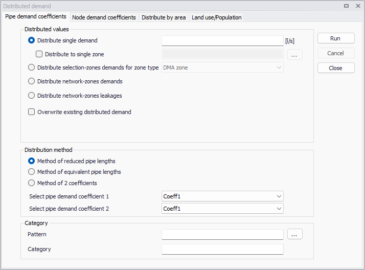
Figure: Distributed Demands Pipe Demands Coefficients
A list of the attributes for the Distributed Demands tool follows.
- Distribute single demand: This option is used to specify the network demand for a particular network pressure zone or the entire network system. Note that this total demand represents the total demand regardless into which multiple junction demand is distributed. Multiple demands are specified in the junction Editor or in the Multiple Demand Editor.
- Distribute to single zone: When this check box is active, the specified water demand value is distributed to a single zone. This zone is selected in the field next to the check box. The zone ID can also be selected from the list using the '…' button. When this check box is unticked, the specified water demand is distributed to the entire water distribution network.
- Distribute selection-zones demands for zone type: This option distributes the specified water demands to zones defined with a selection, and with the zone type selected in the drop-down list. All relevant zones are then listed in the table underneath, where the water demand going to be distributed for each of the zone can be seen. These water demand values are specified in the 'Zones' editor in the 'Demand' field, where they can be adjusted before running the tool, if required.
- Distribute network-zones demands: This option distributes the specified water demands to zones defined as network zone (i.e. with the zone ID specified in the network features). All relevant zones are then listed in the table underneath, where the water demand going to be distributed for each of the zone can be seen. These water demand values are specified in the 'Zones' editor in the 'Demand' field, where they can be adjusted before running the tool, if required.
- Distribute network-zones leakages: This option distributes the specified leakage values to zones defined as network zone (i.e. with the zone ID specified in the network features). All relevant zones are then listed in the table underneath, where the leakage going to be distributed for each of the zone can be seen. These leakage values are specified in the 'Zones' editor in the 'Leakage estimate' field, where they can be adjusted before running the tool, if required. Leakages are then computed as an additional demand at junctions in the zone.
- Overwrite existing distributed demand: When the tool is run, new junction demands are added to the 'Multiple demands' editor, with a 'Mark' indicating that the demand has been computed by the 'Distributed demand' tool.
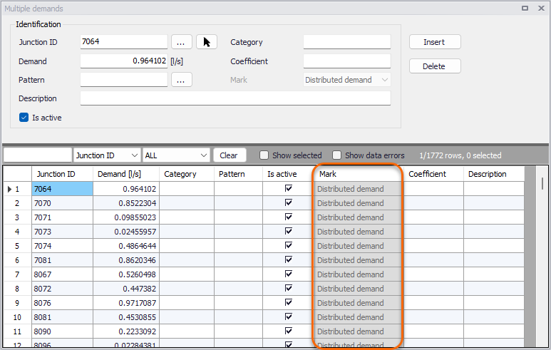
Figure: Mark added by the 'Distributed demand' tool in the 'Multiple demands' editor
When the ‘Override existing distributed demand’ check box is active, the tool will remove the existing demands / leakages (with the same mark) in the junctions first before distributing the new ones. If unticked, the new computed demands / leakages will be added to existing ones.
Method
MIKE+ allows to compute the nodal water demands based upon the total network demand using two methods: the Method of Pipe Lengths and the Method of Two Coefficients.
Selecting the Method of Two Coefficients, MIKE+ computes the total water demand assigned to each pipe (which is then split between the starting and ending nodes) as:
(4.1) 
Selecting the Method of Reduced Pipe Lengths, MIKE+ computes the total water demand assigned toe each pipe (which is split between the starting and ending nodes) as:
(4.2) 
Selecting the Method of Equivalent Pipe Lengths, MIKE+ computes the total water demand assigned to each pipe (which is then split between the starting and ending nodes) as:
(4.3) 
where:
- \(q_{pi}\) = Total water demand applied to the pipe, split between the two end nodes
- \(Q\) = total network water
- \(l_{i}\) = Pipe length
- \(k_{1i}\), \(k_{2i}\) = pipe demand coefficients
- \(k_{Di}\) = pipe demand coefficient, is calculated by the program as a factor, calculated as pipe diameter/diameter_normal (where diameter normal is 150mm or 6 inch). This helps to scale the pipes based on their diameter i.e. perimeter, this method is recommended when the distributed demand corresponds to the amount of leakage.
These demand coefficients are defined for each pipe using the 'Pipes' editor. The computed demands, which are assigned once 'Compute' is selected, are stored at each individual node. There demands are stored in the Junctions Editor. Selecting 'Cancel' will cancel the computation of demand distribution. Selecting 'Close' will close the tool dialog.
Select Pipe Demand Coefficients 1,2
This list allows to specify the demand coefficient, which will be used for demand coefficient 1 or 2. There are four possible pipe demand coefficients, which can be defined for each pipe.
Category
The 'Category' group box holds two attributes:
- Pattern: This data entry allows to define the ID of the demand pattern to be applied to the distribute demand.
- Category: this entry allows to select the category type identifying the consumption point being defined.
Node demand coefficients
Node demand coefficient allows, for each node, to define the share from the whole network demand, which is taken by that node. The total network demand is then distributed to the corresponding junction nodes by Demand Distribution function.
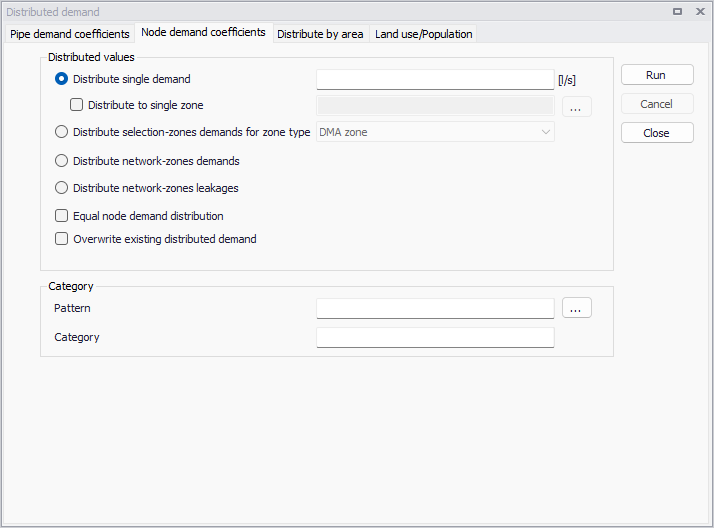
Figure: Node Demands Coefficients
This option will only assign demand to nodes with Demand Coefficient applied (different from 0 or NULL). In the case of an equal distribution, the node demand coefficients have to be equal and different from zero.
It is possible to distribute the water demand by node demand coefficient. Most of the distribution settings are identical to those used for the Pipe demand coefficients method.
Equal node demand distribution
This check box allows the user to distribute the network (or zone) demand equally to each node within the zone or network
(4.4) 
Where:
Q = Total network water demand (or zone demand)
qni = calculated demand at each junction node
N = junction nodes count with the selected zone or a total network
Category
The 'Category' group box holds two attributes:
- Pattern: This data entry allows to define the ID of the demand pattern to be applied to the distribute demand.
- Category: This entry allows to select the category type, which will be used as a target demand for the distributed demand. If the multiple demand with the specified category does not exist, the program will create it and it will override the existing values in case such demand category already exist for each node used in the demand distribution.
Distribute by area
Distribute by Area allows to distribute demands by the ratio of service area of each node. The service area can be defined by Thiessen polygon method or other external source of data, i.e: a feature shape file. External layers needs to be imported to the map previously to be used by the tool.
The user will specify the water demand to be distributed amongst the service areas through the 'Total network water demand'.
The 'Service Area Layer' points at the shape file loaded to the map that can be used as area layers or the generated Thiessen polygon layers.
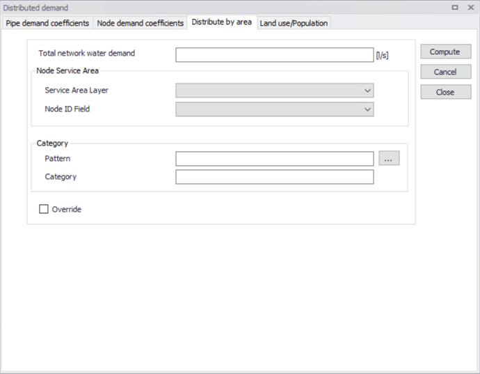
Figure: Distributed Demands Area
The 'Node ID field' defines the Junction ID for each area. The pattern and category can also be specified here.
Land use/Population
The water demands can be distributed by means of the Land use/Population specified for the service area of each node. Similarly to the distribution by Area the user can use Thiessen Polygons or external layers such as feature shape files.
Selecting “Land use” will enable the user to select an external layer of population and the Type Fied.
The user must define the unit demand of each type in the “Use Type” table, this data regards the water demand per hectare (ha) per day. Further the engine will compute the demand for each node and distribute to them.
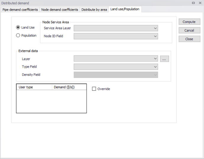
Figure: Distributed Demands Land use
Selecting “Population” will enable also the option to select the Density Field. By choosing this option the user must specify an external layer of population and identify the field of population types. It is required to identify which field in the shape layer contains the population data. Similarly to Land Use it is required to specify the unit demand of people per each type in the table (water demand per capita per day). The engine will compute the water demand for each node and distribute to them.