Tanks
Tank nodes are placed at points in the water distribution model where a water storage tank is located. Storage tanks can be defined as tanks with the variable or fixed water level. The tank with the variable water level are modeled as tanks where the water surface level changes with time as water flows into and out of the tank. The tanks with the fixed water level represent places (reservoir) within the water distribution model where an infinite source of water (for the sake of the modeling simulation) is available. Hence, the reservoir water level remains constant during the course of the simulation.
Tank nodes are either defined interactively on the graphical Map window using the Add Tank tool (see figure below), or by manual data entry using the Tank editor. The Tank editor allows to define the reservoir’s ID, location, properties, water quality, and description.

Figure: The tank editing tool
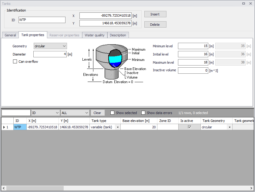
Figure: The Tanks editor allows to define the storage tank nodes that supply water to the distribution network
The Tank Editor contains input fields for geometry, Tank Properties, Reservoir Properties and Description.
A list of the Tanks editor's attributes follows, with a short description given for each one.
Identification
Tank ID
This data entry is used to specify an ID which uniquely identifies the tank node. The tank ID acts as a unique lookup key that identifies the node from all other nodes. A node can be a junction, reservoir, tank, or air-chamber. Therefore, no two nodes may have the same ID.
However, a node and a link (i.e., pipe, pump, or valve) can have the same ID. The node ID value can be any string value (up to 40 characters).
X and Y coordinate
The X and Y data entries are used to define the physical (map) location of the tank node, in units of ft. or m.
General
This tab gives general information of tanks.
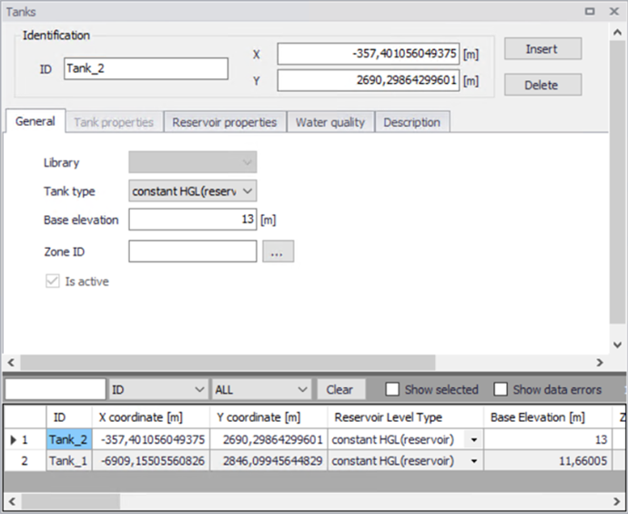
Figure: The general information of tank
Tank Type
This drop down selection list data entry allows you to define whether the tank is modelled as reservoir (constant HGL), or is tank (variable HGL).
There are two options available:
- Constant HGL (Reservoir)
- Variable HGL (Tank).
Base Elevation (mandatory)
Base elevation defines the distance from bottom of the tank/reservoir above datum elevation.
Zone ID
This is an optional name for the zone to which the tank belongs. When a zone ID is specified, this zone will be listed in the 'Zones' editor. The '…' button can be used to select an existing zone.
Is Active
This check box controls whether the tank will be included (when ticked) or omitted (when unticked) in the simulations. The tank is automatically omitted as soon as all connected links are also set to inactive.
Tank Properties
This tab is editable only when the tank type is “variable (tank)”.
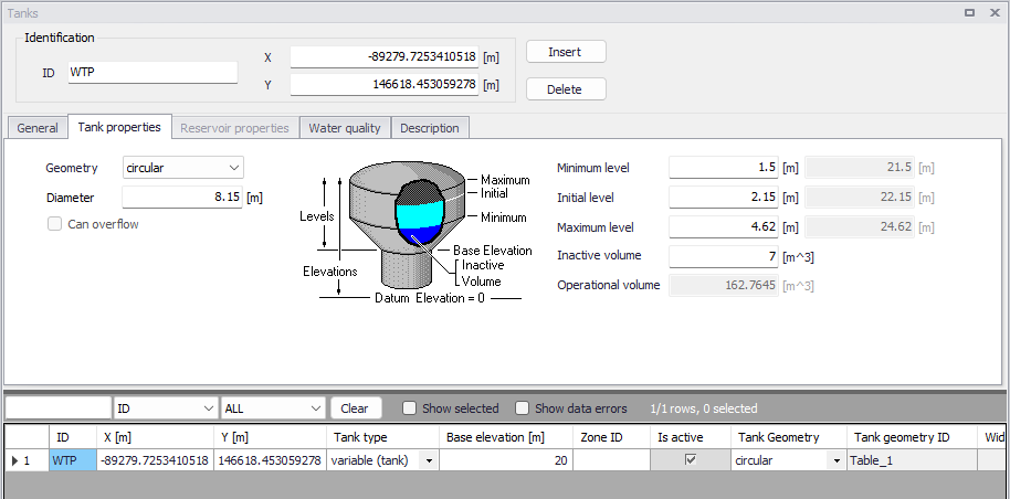
Figure: The tank properties
Geometry (mandatory)
This drop down selection list data entry selects the type of storage tank being defined.
- Table
- Rectangular
- Circular.
For different types of tank, the required geometry data is different. By default, a circular tank is defined. The elevation-volume relationship for a tank of variable geometry is needed to be defined. A Volume Curve determines how storage tank volume (Y in cubic feet or cubic meters) varies as a function of water level (X in feet or meters). It is used when it is necessary to accurately represent tanks whose cross-sectional area varies with height. The lower and upper water levels supplied for the curve must contain the lower and upper levels between which the tank operates.
Geometry ID (mandatory)
The geometry ID is the ID of the relationship which determines how storage tank volume (Y in cubic feet or cubic meters) varies as a function of water level (X in feet or meters). It is used when it is necessary to accurately represent tanks whose cross-sectional area varies with height. This relationship is defined in the 'Curves and relations' editor, using the curve type 'Tank depth-volume'
Diameter / Width and Length (mandatory)
These allow to define the tank chamber size.
Can overflow
When this option is selected, any inflow to a full tank becomes overflow (i.e. spillage). When it's unselected, any link that would normally send flow to the tank is temporarily closed when the tank is full. This option is only available when using the EPANET 2.2 version.
Minimum level (mandatory)
This data entry defines the minimum level (or depth), in units of ft. or m, that the water can drop to within the storage tank. The corresponding elevation is equal to the base elevation plus the minimum level.
Initial level (mandatory)
This data entry defines the initial water surface level (or depth), in units of ft. or m, that is used at the start of the simulation. The corresponding elevation is equal to the base elevation plus the initial level.
Maximum level (mandatory)
This data entry defines the maximum level (or depth), in units of ft. or m, that the water can rise to within the storage tank. The corresponding elevation is equal to the base elevation plus the maximum level.
Inactive volume (optional)
This data entry defines the volume of inactive water contained between the minimum level and the base elevation, in units of \(\text{ft}^{3}\) or \(\text{m}^{3}\), of the storage tank.
Operational volume
This volume is derived from the above geometrical properties of the tank, and represents the usable volume, which can be filled or released from the tank.
For circular and rectangular tanks, the volume equals the horizontal area of the tank times the difference between its maximum and minimum water levels.
For tanks defined using a geometry table, the operational volume is the difference between the volume of the table at the maximum level, and the volume of the table at the minimum level. Volumes at the maximum and minimum levels are obtained using a linear interpolation from the table's data.
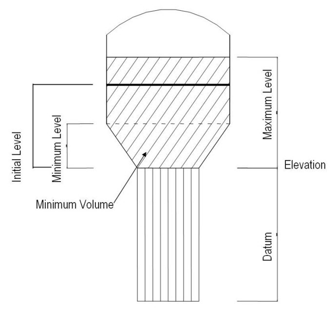
Figure: Definition of storage tank levels
Reservoir Properties
This tab is editable only when the tank type is “Reservoir”.
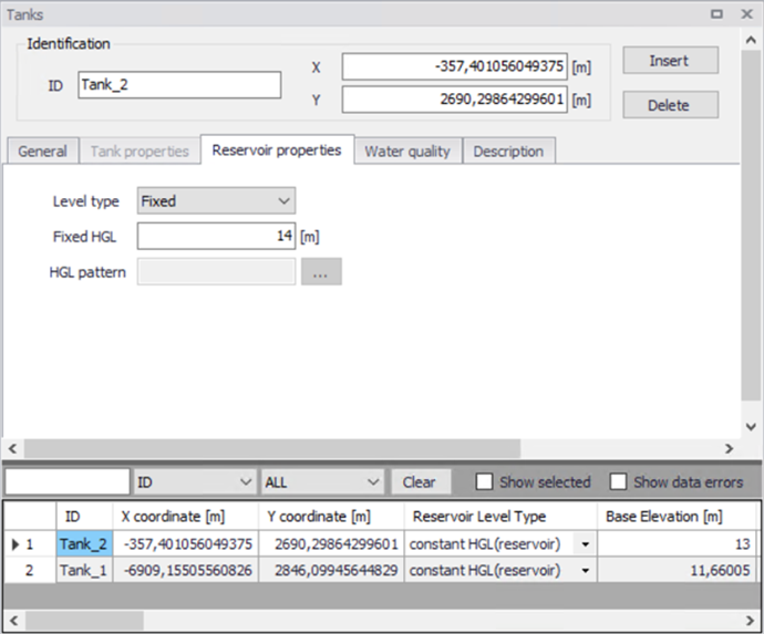
Figure: The Reservoir Properties
Level type
This data determines whether the total water head of reservoir is fixed or variable. There are two options available for the level type:
- Fixed
- Pattern.
Fixed HGL
This data entry allows you to define the constant water head in case that the tank is modelled as a reservoir with fixed water level. The water head is defined in ft or m.
HGL pattern
The ID label of a time pattern used to model time variation in the tank’s (reservoir's) total head. This property is useful if the reservoir represents a tie-in to another system whose pressure varies with time.
Water Quality
This tab defines water quality parameters of tanks.
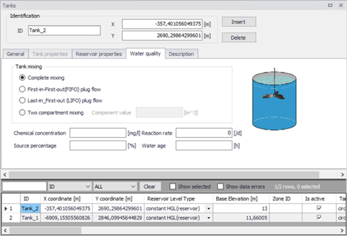
Figure: The water quality parameters of tanks
Tank mixing (optional)
MIKE+ allows to choose between four different types of tank mixing, completely mixed, two compartment mixing, Last In First Out (LIFO) and First In First Out (FIFO).
The Completely mixed model assumes that all water that enters a tank is instantaneously and completely mixed with the water already in the tank. It is the simplest form of mixing behavior to assume, requires no extra parameters to describe it, and seems to apply quite well to a large number of facilities that operate in fill-and-draw fashion.
The Two-Compartment mixing model divides the available storage volume in a tank into two compartments, both of which are assumed to be completely mixed. The inlet/outlet pipes of the tank are assumed to be located in the first compartment. New water that enters the tank mixes with the water in the first compartment. If this compartment is full, then it sends its overflow to the second compartment where it completely mixes with the water already stored there. When water leaves the tank, it exits from the first compartment, which if full, receives an equivalent amount of water from the second compartment to make up the difference. The first compartment is capable of simulating short circuiting between inflow and outflow while the second compartment can represent dead zones. The user must supply a single parameter which is the fraction of the total tank volume devoted to the first compartment.
The First-In-First-Out (FIFO) Plug Flow mixing model assumes that there is no mixing of water at all during its residence time in a tank. Water parcels move through the tank in a segregated fashion where the first parcel to enter is also the first to leave. Physically speaking, this model is most appropriate for baffled tanks that operate with simultaneous inflow and outflow. There are no additional parameters needed to describe this mixing model.
The Last-In-First-Out (LIFO) Plug Flow mixing model assumes that there is no mixing between parcels of water that enter a tank. However in contrast to FIFO Plug Flow, the water parcels stack up one on top of another, where water enters and leaves the tank on the bottom. Physically speaking this type of model might apply to a tall, narrow standpipe with an inlet/outlet pipe at the bottom and a low momentum inflow. It requires no additional parameters be provided.
Reaction rate (optional)
This data is locally defined reaction rate. It defines the rate at which constituent decays (or grows) by reaction as the constituent travels through the pipe network. Please refer to section on reaction rates for further.
Chemical concentration
This data entry is used to specify the initial water quality (chemical concentration in mg/liters) at the tank. It is used when conducting chemical concentration simulation.
Source percentage
This data entry is used to specify the initial percentage of water from the source node in percent at the tank. It is used when conducting source tracing simulation.
Water age
This data entry is used to specify the initial water age of water in hour at the tank. It is used when conducting water age simulation.
Description
Description
This data entry allows you to enter a description identifying the tank node being entered. This description can be optionally displayed on the Map window and in reports generated by the Report Generator.
Data source (optional)
This data entry is used to specify a corresponding asset data source, which uniquely identifies the tank node location (such as database table or a database file name) in the asset management system.
Asset ID (optional)
This data entry is used to specify a corresponding asset tank ID, which uniquely identifies the tank node in the asset management system (such as GIS, for example).
Status (optional)
This drop down selection list data entry allows you to define whether the tank node is imported (i.e existing node was imported from the external data source), or is inserted, modified, GIS, calibrated or similar. By default, tank node status is undefined.
Add picture
The 'Add picture' button allows to add photo for individual tank. Once loaded from external source, the picture will be displayed on the right side.
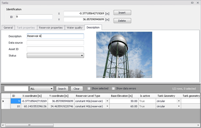
Figure: Tank's picture