Gates
Gates may be used whenever structure flow is to be regulated by the operation of a movable gate forming part of the structure. The Gates editor contains the physical properties of the structures, while the rules regulating it are defined in the Control rules editor.
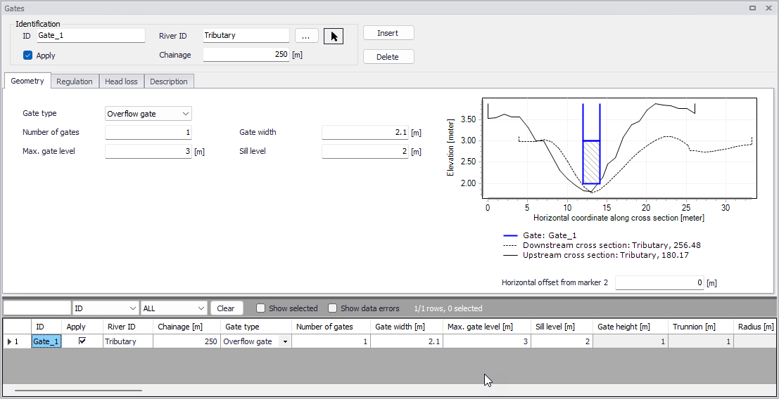
Figure: The Gates editor accessed via the River Network setup group
Identification
The Identification group holds basic information on gates.
ID
Unique string identification for the gate.
River ID
The ID of the river branch where the gate is located. The River ID is automatically registered if the gate is created via the Map. Use the button with an arrow, to select the location of the structure on the map: this will specify both the River ID and the Chainage of the structure.
Chainage
Chainage at which the gate is located.
Apply
This check box allows the user to toggle the Active status of the gate on and off. The simulations will omit all gates that are not active.
Geometry
Geometric properties for the gate are defined on the Geometry tab page of the gates editor.
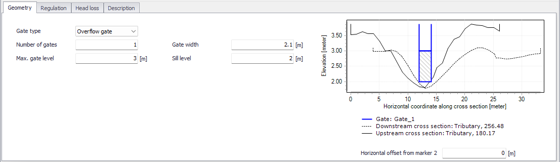
Figure: Geometry tab on the Gates editor
Define properties such as:
Gate type
The following options are available to define the gate type:
- Overflow gate: This gate type corresponds to a variable crested weir, describing the flow over the weir.
- Underflow gate: This gate type corresponds to a vertical sluice gate, describing the flow below the gate.
- Radial gate: This gate type corresponds to a Tainter gate. In contrast to the other gate types a radial gate does not need any information about head loss factors. Instead a number of radial gate parameters must be entered, see the Flow parameters section.This gate type describes both the flow below and over the gate.
- Sluice gate: This gate is physically the same as an underflow gate but instead of using the energy equation a set of flow formulas are applied, see the Flow parameters section. This gate type describes both the flow below and over the gate.
Number of gates
Number of parallel and identical gates. All these gates will inherit the same control rules and will therefore have the same gate level.
Gate width
The width of the gate.
Max. gate level
The highest possible gate level.
Sill level
The level of the sill just upstream of the gate.
Gate height
Parameter specified for radial gates and sluice gates. Height of the overflow crest above sill level when the gate is closed. See figure below for radial gates.
Trunnion
Parameter specified for radial gates only. Height of the center of gate circle above sill level, see figure below.
Radius
Parameter specified for radial gates only. Radius of gate, see figure below.
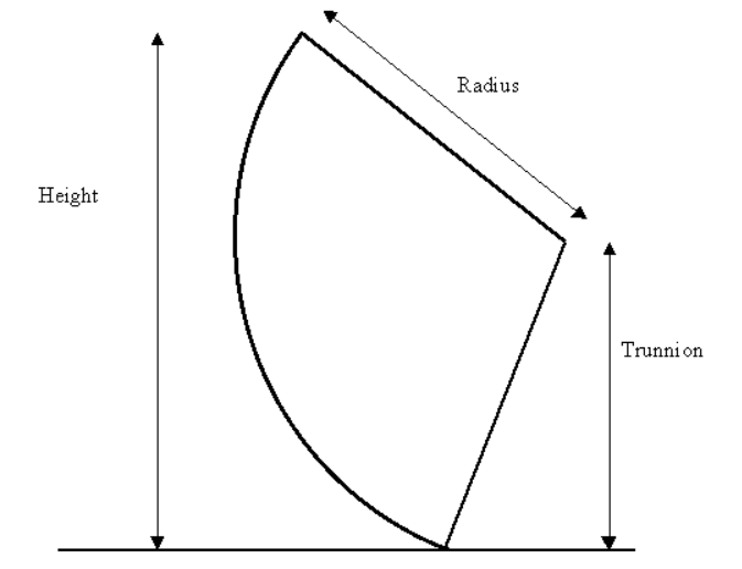
Figure: Definition of a radial gate
Structure plot
To help ensuring that the geometry of the gate is properly defined, the gate's shape is shown and is compared to its upstream and downstream cross sections. On this plot, the horizontal axis shows the X-coordinates from the upstream cross section. The downstream cross section is then shifted so that its marker 2 is aligned with the marker 2 from the upstream cross section. The gate shape is also centered around this marker 2, but can be moved horizontally using the value 'Horizontal offset from marker 2'.
Note
This horizontal offset value is only used for the visualization purpose and has no impact on the simulation.
On the gate's shape, the area with hashes shows the area in which the gate can evolve, i.e. the area below the maximum gate level. It does not represent the actual / instantaneous gate level that will be computed during the simulation. For a radial gate, this is only the maximum level of the bottom of the gate, but the overflow will still be enabled in the simulation above this area with hashes.
Regulation
Regulation settings (other than the control rules) of flows through the structure may be set in the Regulation tab page of the Gates editor.
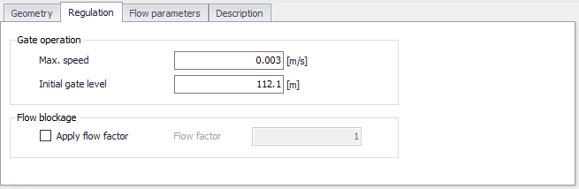
Figure: The Regulation tab on the Gates editor
Max. speed
Defines the maximum allowable change in gate level per time.
The maximum speed represents the physical maximum speed of the gate, and may be used to avoid very rapid changes in gate level. Such rapid changes could appear from some control rules but in case they are not realistic they would potentially create instabilities in the computation.
Initial gate level
The value specified will be used as initial gate level at the beginning of the simulation.
Apply flow factor
When this option is active, the discharge computed through the gate is multiplied by a flow factor. This factor's value is specified in the Flow factor field. The factor is a dimensionless factor, and a value of 1 means that no change is applied to the computed discharge. A value lower than 1 can typically be used to describe the reduction of the flow through the structure due to obstacles, like debris, restricting the flow area in the structure.
Head Loss
Define head loss parameters for an overflow or underflow gate on the Head Loss tab page of the gates editor.
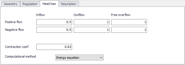
Figure: The Head Loss tab of the Gates editor
Head loss variables are included in the calculation of the energy loss occurring for flows through hydraulic structures.
Positive/Negative flow
Local head loss factors are defined for Inflow (entrance), Outflow (exit) and Free overflow (calibration factor). Different loss factors may be distinguished depending on the flow direction across the structure.
Contraction coef.
This is the contraction coefficient used for underflow gates only.
Computational method
Two computational methods are available:
- Energy equation: with this method, the flow through the structure is solved using the energy equation, in order to compute the discharge in the structure as a function of the head loss factors. The computed discharge is then applied at the calculation point. This is the preferred option in case there are big changes in cross sections before and after the structure, or if the flow area of the structure is much less than that of the river.
- Shallow water equation: with this method, the flow through the structure is solved adding a head loss term to the shallow water equation (Saint-Venant momentum equation), this term being a function of the head loss factors. With this method, the same equation is applied at structures' locations as at other regular calculation points (without structures). This ensures a continuity of the results between the upstream / downstream reaches and the structure, e.g. also including a bed friction between the upstream and downstream cross sections of the structure. Additionally, this method also enforces the use of velocity in upstream and downstream cross sections to compute the head loss, instead of using the velocity in the structure. This option is mainly designed for scenarios where the structure creates little or no head loss for low water levels, as e.g. for an overarching bridge. See the "Head loss mode" in the MIKE 1D reference manual, for more information.
Note
When the flow through the structure becomes supercritical, the applied method is always the Energy equation. Besides, the 'Shallow water equation' method cannot be applied for structures located on rivers of type 'Structure link'. When several structures exist at the same location, if any of them uses the Shallow water equation method, then all other structures at the same location will also apply the same equation no matter the selected method in their properties.
Flow parameters
Flow parameters for radial gates and sluice gates are shown in the Flow parameters tab page of the Gates editor. The parameters to be specified are different for radial gates and for sluice gates.
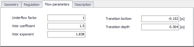
Figure: The Flow parameters tab for a radial gate
For radial gates, the structures are automatically divided into an underflow part and an overflow part. When specifying gate levels for a radial gate, the user should specify the level for the underflow part, i.e. the level of the bottom of the gate. The gate level for the overflow part is then calculated based on geometric considerations.
Flow through a radial gate is calculated as a function of the flow regime of the gate (either 'Free', 'Submerged' or 'Transition'). Free and Submerged flow regimes are calculated individually as described in 'Hydraulic Aspects - Radial Gates' in the MIKE 1D Reference Manual and flow in the transition zone is calculated as an interpolated value between the calculated Free and Submerged flows.
The following parameters are used for radial gates.
Underflow factor
Discharge calibration factor. The factor is applied as a multiplication factor solely on the part of the discharge that flows below the radial gate (not applied to eventual overtopping gate flow).
Weir coefficient
Coefficient used in the calculation of eventual flow above the top of the radial gate (considered as weir flow above the top of the radial gate).
Weir exponent
Exponent used in the calculation of eventual flow above the top of the radial gate (considered as weir flow above the top of the radial gate).
Transition bottom
The Transition bottom parameter is an offset used to define the level where a free flow regime for the gate changes to a transition zone between free flow and submerged flow regime. It corresponds to yTran,Bottom as defined in 'Hydraulic Aspects - Radial Gates' in the MIKE 1D Reference Manual.
Transition depth
The transition depth parameter is used to define the depth (or height) of the transition zone between free flow and submerged flow regimes and consequently is used to define the level where the flow regime changes to submerged flow. Corresponds to yTran,Depth as defined in 'Hydraulic Aspects - Radial Gates' in the MIKE 1D Reference Manual.
For a sluice gate, the flow under the gate is divided into four flow regimes, the choice of which depends on the upstream and downstream water levels. The four flow regimes are:
- Controlled submerged
- Controlled free
- Uncontrolled submerged
- Uncontrolled free.
Additionally, the flow over the top of the sluice gate is taken into account when the water level upstream and/or downstream exceeds the gate level plus the gate height.
The following parameters are used for sluice gates, for the different flow regimes.
Coef. a
Coefficient a of the flow equation for the four different flow regimes.
Exp. b
Exponent b of the flow equation (it does not apply to the uncontrolled free flow).
High limit and low limit
High limit and low limit parameters used to smoothen the transitions between flow regimes (they do not apply to the uncontrolled free flow).
Please refer to the chapter 'Hydraulic Aspects - Sluice Gates' in the MIKE 1D Reference Manual for further details on the flow at sluice gates and to see the equations used in the computations.
Description
Use the Description tab to add free text descriptions for gates. It offers options for providing model management information, as well as attributes for quick model data query.
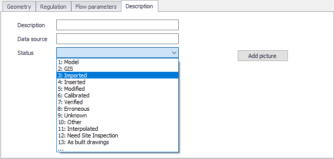
Figure: The Description tab on the Gates editor
- Description: Free text description for the gate.
- Data source: Free text describing data source for gate data.
- Status: Project-defined status information that may be used for model build management or e.g. model data query. Pre-defined codes are contained in the Status Code editor which may be accessed via the ellipsis button from the Status dropdown menu.
- Add picture: Option for adding images associated with the gate structure.