Zone Mapping
Create zones from network separators
This tool creates zones based on the network topology and geometry, closed pipes, closed valves, and pumps.
Defining zones helps to visualise how different network parts are hydraulically interconnected and where the HGL line breaks. It helps understand the hydraulic behaviour of the network prior to running the hydraulic simulation, and also helps detect possible errors in the network connectivity.
Launch the ‘Create zones from network separators’ tool from the 'WD Network' tab of the ribbon.

On the ‘Create zones from network separators’ dialog, define the breakdown rules of the network, the separators, and the rules for merging small groups of pipes into one big group:
- Separators: Separators are links, which will be used to separate one zone from another. Separators can be:
- Closed link: any type of closed link will separate zones, e.g. pipes, valves or pumps.
- Pump: all pumps will act as separator, regardless of their opened / closed status.
- Vale types (PRV, PSV, PBV, FCV, TCV, GPV) : all selected valve types will act as separator, regardless of their status (regulating / opened / closed).
- Check valve
- Merge zones smaller than: In case that there are many small zones (a typical example would be small pipes located in pumping stations and storage tanks), they will be all merged into the same zone for graphical display instead of creating a separate zone for each of them.
- Save zones: The user can decide whether to save the zones to the zone editor or not. A zone category should be defined, then it would automatically create all zones named after the category, e.g. Zone_mapping_1.
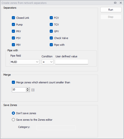
Figure: The ‘Create zones from network separators’ dialog
Run the analysis using the ‘Run’ button. This produces a result layer, which is automatically loaded on the Map.
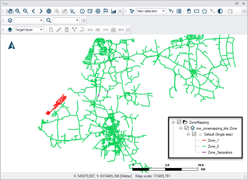
Figure: Example Zone Mapping result plotted on the Map
Running the tool also automatically generates a report with information of different zones, such as the number of links in each zone, the number of separators and merged zones.
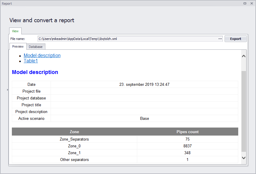
Figure: Example Zone Mapping report
Create zones from GIS layer
This tool automates the creation of new zones using a polygon shape file to read the zones' extents from.
Defining zones helps to visualise how different network parts are hydraulically interconnected and where the HGL line breaks. It helps understand the hydraulic behaviour of the network prior to running the hydraulic simulation, and also helps detect possible errors in the network connectivity.
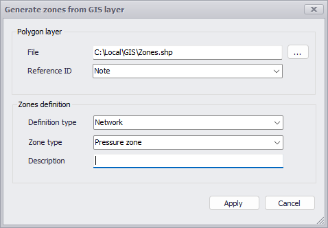
Figure: Creating new zones from a GIS layer