Simplification Tool
Introduction
'Model simplification' is the term associated with the process of removing disconnected and unnecessary model elements, removal of model parts outside an area of interest and eliminating internal nodes which appear as redundant and insignificant for the hydraulic computations or for any other use of the model data.
Simplification reduces the complexity of a model which improves the efficiency of the computations. Correct simplification shall not compromise the integrity of the model and shall not affect the model's accuracy significantly.
Simplified models are used in different contexts - for the computations where time-efficient computation is of crucial importance, such as online model applications, long term simulations, strategic scenario analyses, etc., or for the presentation purposes.
Launching the Tool
The MIKE+ model simplification tool works with WD and CS models. The tool is found in the ribbons under 'WD Network' or 'CS Network' , under Special tools Network simplification (figure below).
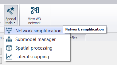
Figure: Launching the Network simplification tool
When activated, a wizard-like tool opens (figure below). The wizard includes several pages, each dedicated to a specific stage in the simplification process. Access to various pages goes through page selector in the left side. The pages accessible through the page selector depend on the actual context.
The sequence of pages in the menu suggests the preferred workflow.
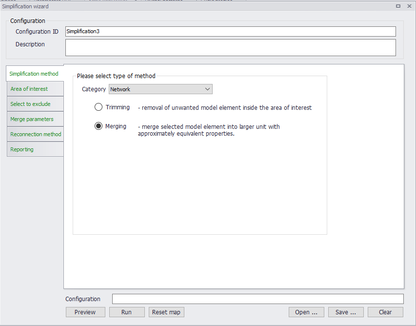
Figure: The Simplification tool
Simplification Categories and Methods
The simplification tool supports the following categories:
- Network: this category deals with reducing the network's complexity by removing nodes and pipes. The applicable methods are:
- Trimming: This is about removing disconnected and regular parts of the network, selected by spatial or attribute-based filters, and/or manually. The catchments of CS models and boundary conditions attached to the removed network elements are automatically reconnected to the remaining network.
- Merging: This is about removing nodes along a stretch of conduits and merging several conduits into one, equivalent conduit. The catchments of CS models and boundary conditions attached to the removed nodes are automatically reconnected to the remaining nodes or directly to the conduit.
- Catchments: this category deals with catchments. The only simplification method available for catchments is merging of multiple sub-catchments to larger units. The original parameters for the hydrological model are re-calculated for the merged catchment. The merged catchment is re-connected automatically, according to user's specification.
- Surrogate: this category deals with converting a simplified "skeleton" network model into an equivalent network composed of orifices connecting basins.
The network simplification methods ("Trimming" and "Merging" are available for both CS and WD networks.
"Catchments" and "Surrogate" simplification categories are only available for the CS network.
Simplification Procedure
The simplification procedure includes several steps, each associated with the wizard pages:
-
Simplification Method: Here the simplification category and method are selected. Depending on the choices on this page, other pages are made accessible or hidden
-
Area of interest: In this page several various filters (both inclusive and exclusive) are available to select parts of the model that will participate in the simplification operation. This is relevant for all simplification categories and methods.
-
Select to exclude: Selection filters in this page operate on previously selected "Area of interest", to EXCLUDE the selected model elements from the simplification process. Typically, excluded elements are those that are essential for the model integrity. This is relevant for all simplification categories and methods.
-
Trimming Parameters: Includes a collection of parameters that control the network trimming process. This is only relevant when the selected simplification category is "Network", and the method is "Trimming"
-
Merge parameters: Includes a collection of parameters for the merge operation. Separate pages are available for network merge and for catchment merge operations. This is relevant when the selected simplification category is "Network" or "Catchments", and the method is "Merging"
-
Surrogate parameters: Includes a collection of parameters for the creation of "surrogate" hydraulic model. This is only relevant when the selected simplification category is "Surrogate"
-
Reconnection method: Contains specification for reconnecting catchments and boundary conditions, orphaned after removal of their original connection locations
-
Reporting
Each of the above steps are explained in detail in the following sections.
It is possible to save the simplification settings from the current session into an *.XML configuration file. Also, previously stored configurations can be open in the wizard, so that the simplification operation can be repeated on a different/updated model.
This functionality is available at the bottom of the network simplification wizard. When the *.XML file is opened, the settings in all dialogs will be filled to reflect the saved configuration.
Simplification method
The first thing to do is to select the wanted simplification category, and in case of "Network", the wanted simplification method.
The choices made in this page control the accessibility the remaining relevant pages with parameters for the configuration of the simplification operation. Content of some pages is adjusted automatically, depending on the actual context.
Area of interest
The parts of the model area that will be subject to the selected simplification method are defined on the tool's page "Area of Interest". User has several mutually exclusive and inclusive filters at disposal. The types of filters that are available depend on the actual simplification category.
"Area of interest" for the "Network" and "Surrogate" simplification categories
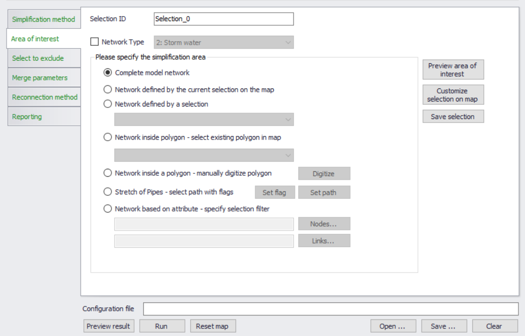
Figure: Area of interest page for "Network" and "Surrogate" simplification category
For the "Network" (both CS and WD networks) and for CS "Surrogate" categories, the area of interest is based on the selections of network elements - nodes and links. The following filters are available:
- Network type: Per default, this is not activated. This means that the chosen simplification method will act on all otherwise included model elements, independently of their "network type" attribute. This is recommendable for the models comprising only one type of drainage network. When activated by a checkmark, this filter limits the simplification operation to the selected type of network. Obviously, this requires that the "network type" attributes are consistently and correctly applied to all model elements.
The "network type" filter works jointly with the other available filters. - Geographical and attribute-based filters: These filters are mutually exclusive, i.e. the specified "area of interest" is based on one of the filters only.
- Complete model network: This is the tool's default setting. This is an unfiltered selection
- Network defined by the current selection on the map: When selected, area of interest is limited to the model elements that are marked as selected on the map, independently on how this selection has been created
- Network defined by a selection: This filter includes a reference to an existing selection in the "Selection manager"
- Network inside existing polygon: This filter limits the simplification to model elements inside e.g. selected sub-catchment polygons.
- Network inside manually digitized polygon: This filter limits the simplification to model elements inside a polygon digitized "on-the-fly".
- Stretch of pipes - select with flags: This filter is applicable for the network merging method and for "Surrogate" simplification. It limits the merging or surrogate operation to a specified stretch of pipes.
- Network based on attributes: Predefined filters (for nodes and/or links) in SQL format can be loaded and employed.
Pre-viewing and customizing the "Area of Interest" selection
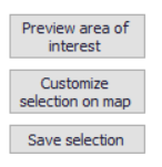
Figure: Action buttons on the "Area of interest" page
Action buttons "Preview area of interest", "Customize selection on map / Commit selection on map" and "Save selection" provide (optionally) useful functionalities, that support the selection process.
"Preview area of interest" highlights on the map all the model elements selected by the activated filters.
If this is not satisfactory, pressing "Customize selection on map" turns the highlighted element to the actual selection, allowing that user "manually" (i.e. using the map selection tools) customizes the selection generated by the active filters, by adding or removing some elements from the selection.
While in "customize" mode, the button changes to "Commit selection on map". When pressed upon completed customization, this button turns the current selection to highlights.
If wanted, the currently highlighted or selected elements are saved into the "Selection manager" as a new selection by "Save selection" button. This new selection is given a generic ID, that needs to be replaced by some meaningful ID for easy identification.
"Area of Interest" for the "Catchments" category
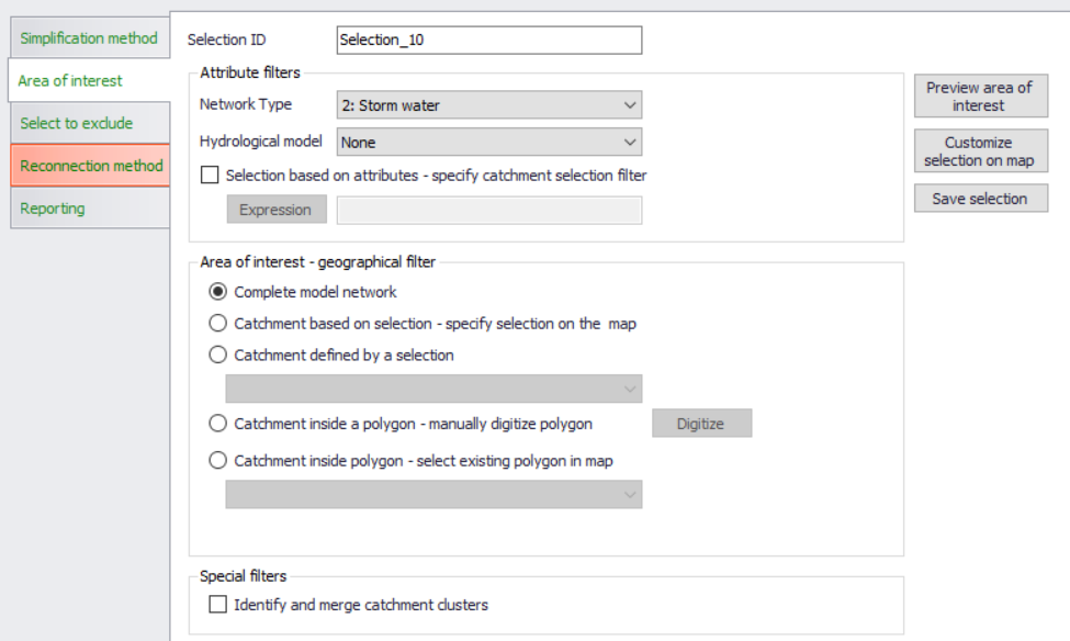
Figure: Area of interest page for "Catchments" simplification category
For the "Catchments" simplification category, the area of interest is based on the selections of catchments. The following filters are available:
- Network type: This filter limits the catchment merging operation to the catchments attributed to belong to one network type at a time (as per the 'Network type' defined in the 'Catchments' editor, in the 'Description' tab). This means that the catchment merging in the models containing catchments belonging to various network types would require several subsequent runs of the tool. Obviously, this tool requires that the catchments are consistently attributed by network type or, alternatively, remain undefined.
This filter works jointly with the hydrological model filter, the generic attribute filter, and the activated geographical filter. - Hydrological model: The tool only merges catchments set up for the same type of hydrological (i.e. Rainfall-runoff) model. I.e. if two or more catchments are to be merged, they all must be set up for the computation with the same hydrological model.
This filter works jointly with the network type filter, the generic attribute filter, and the activated geographical filter. - Selection based on attributes: When activated by checkmark, this filter allows for an additional filtering based on one or more catchment attributes.
This filter works jointly with the network type filter, the hydrological model filter, and the activated geographical filter. - Geographical filters: These filters are mutually exclusive, i.e. the specified "area of interest" is based on one of the filters only. - Complete model network: This is the tool's default setting. This is an unfiltered geographical selection that includes all catchments in the model - Catchments defined by the current selection on the map: When this is chosen, the area of interest is limited to the catchments that are marked as selected on the map, independently on how this selection has been created - Catchments defined by a selection: This filter includes a reference to an existing selection containing catchments in the "Selection manager" - Catchments inside existing polygon: This filter limits the simplification to model elements inside a selected existing polygon feature. - Catchments inside manually digitized polygon: This filter limits the simplification to the catchments inside a polygon digitized "on-the-fly". - Special filter (catchment clusters): A "catchment cluster" is defined as a set of catchments, all set to use the same hydrological model, defined with the same network type, and all connected to the same location in the network. The catchment cluster would typically emerge after a trimming operation, where insignificant, peripheral parts of the network get removed and the orphaned catchments get reconnected to the remaining part of the network.
This filter identifies "clusters" and merges all catchments belonging to one cluster into one catchment.
Select to exclude
"Select to exclude" filters out the model elements that are to remain intact by the actual simplification. This is achieved by several mutually inclusive filters that are applied to the parts of the model previously defined by "Area of interest".
The types of filters and their default settings depend on the actual simplification category and method.
“Select to exclude” for CS network
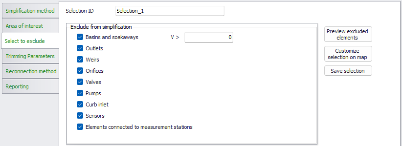
Figure: "Select to exclude" filters for CS network trimming
Per default, in CS network trimming all structures and the associated FROM/TO nodes, all basins and all outlets nodes, as well as all associated links are excluded from the trimming operation. Also, all elements containing sensors or connected to a measurement station are excluded per default. This is to avoid a loss of important functionality of the model in the simplified version.
Optionally, user can relax the default selection by unchecking some of the element types or to limit the max. size of basins to be excluded.
For CS network merging and surrogate, only the filters for basins & soakaways and for sensors can be deactivated. This means that merging operation will only remove plain nodes (manholes and junctions) without any structure attached and, optionally, basins under the specified volume threshold.
For "Surrogate" category all basins are unconditionally excluded from the simplification.
"Select to exclude" for catchment merging
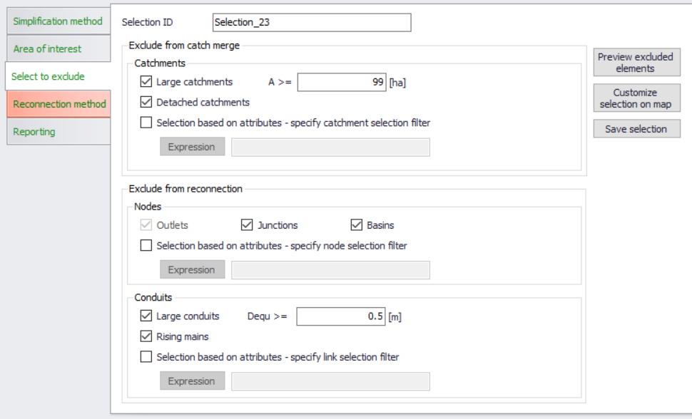
Figure: "Select to exclude" filters for catchment merging
This page contains two sets of exclusion filters:
- Catchment exclusion filters: this serves to exclude certain catchments from the merge process, similarly as it is the case with network elements in network merging or network trimming operations.
- Large catchments (default A >= 99 ha). When activated, this filter will leave out all catchments of the size larger than the specified threshold. I.e. the operation will be limited to smaller catchments only.
- Detached catchments. Catchments that are not properly "snapped", will not be merged.
- Selection based on attributes. This excludes from the merge operation all catchments filtered out by one or more catchment attributes specified here
- Reconnection exclusion filters. After the catchment merge operation, the resulting catchment shall be connected to the network according to the specification (see "Reconnection method" further below). Target for the catchment connection are both nodes and links. Some of these are not eligible for catchment connections by default and some may be excluded optionally by filtering.
- Node (Outlets): Outlet nodes are excluded per default, as connection of catchments to outlet nodes is not allowed.
- Node (Junctions): Junctions typically represent pipe joints without actual connection to the surface. Therefore, junctions are per default excluded as catchment connection points. If wanted, this filter can be de-activated
- Node (Basins): Basins represent water storage facilities, frequently built as underground structures. In such cases they do not have actual connection to the surface, i.e. runoff. Therefore, basins are per default excluded as catchment connection points. If wanted, this filter can be de-activated.
- Node (selection based on nodes attributes): This excludes from the catchment connections any nodes filtered out by one or more node attributes specified here
- Link (Large conduits): When activated, this filter will leave out all pipes of the size larger than the specified threshold (i.e. of the equivalent diameter). So, the merged catchments will be connected to smaller pipes only. Reasoning behind this filter is that the large sewer pipes normally serve as transport conduits, without actual connections to the catchments. If wanted, this filter can be de-activated, or any other threshold size applied.
- Link (Rising mains): per default, rising mains are excluded as targets for catchments connections. If wanted, this filter can be de-activated.
- Link (selection based on links attributes): This excludes from the catchment connections any links filtered out by one or more links attributes specified here
"Select to exclude" for WD network
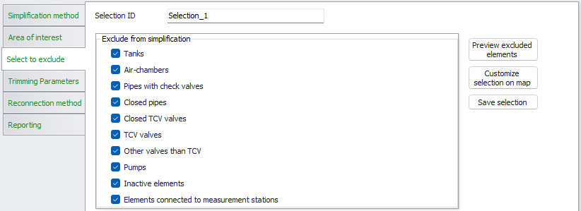
Figure: "Select to exclude" filters for WD network trimming
Per default for WD network trimming, several feature types like tanks, air-chambers, closed pipes, TCV valves, pumps, etc. are excluded from the simplification. Also, all elements connected to a measurement station are excluded per default. This is to avoid a loss of important functionality of the model in the simplified version.
Optionally, user can relax the default selection by unchecking some of the element types.
For WD network merging, only the filters for pipes with check valves, closed pipes, inactive elements and elements connected to measurement stations can be deactivated.
Pre-viewing and customizing the selection
Similar to the "Area of Interest" page, the "Select to Exclude" page provides functionalities for pre-viewing and customizing the selections obtained by the activated filters.
This is achieved by action buttons "Preview excluded elements", "Customize selection on map / Commit selection on map" and "Save selection". The functionality of these buttons is described under "Area of Interest".
Trimming parameters CS Network and WD network
Trimming parameters (CS Network and WD network)
After defining the area of interest and after excluding some model elements from the trimming operation, the actual trimming operation must be configured by setting the trimming parameters.
This is achieved on the "Trimming parameters" page.
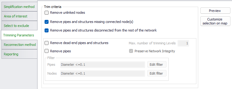
Figure: The "Trimming Parameters" page
"Trimming" means removal of the unwanted model elements from the periphery of the model. Typically, this would include disconnected nodes and pipes, dead-end pipes, small diameter pipes and nodes.
Any selection for trimming is made from the currently defined area of interest, further reduced by the elements specified as "selected to exclude".
The trimming operation is controlled by the following parameters:
- Remove unlinked nodes: "Unlinked nodes" are nodes disconnected from the rest of the network, i.e. with no connection by at least one link (conduit or structure)
- Remove pipes and structures missing connected node(s): these are links missing a 'From' node, 'To' node, or both.
- Remove pipes and structures disconnected from the rest of the network: these are single links, which are not connected to any other link.
- Remove dead-end pipes and structures: "Dead-end pipes" are ending pipes with upstream node type "manhole" or "junction. "Dead-end structures" (CS network) are only relevant if not excluded by the user in the "Select to exclude" page.
- "Remove pipes": This affects any pipes fulfilling the set pipe and node filters, independently on its position in the network. If both pipe and node filters are specified, then both criteria shall be fulfilled to include the pipe in the "Remove pipe". If node filter is specified, it must be fulfilled for both nodes for the pipe to be included in "Remove pipe".
- "Preserve network integrity" is a default option that controls the working of "Remove pipes". When activated, it prevents that the trimming removes pipes that secure the connectivity of the network! E.g. if a pipe fulfils criteria to be removed (D =\<= 0.2 m) but is located somewhere inside the network, it should never be removed.
Note
If any dead-end pipe is removed, then its upstream ("dead-end", i.e. "FROM") node must also be deleted. Alternatively, if pipe orientation is not correct, a remaining orphan node shall be removed, independently if it is defined as "FROM" or "TO".
Removing of any pipe that is not a dead-end pipe, does not affect any of the connecting nodes.
"Max no. of trimming levels" is of relevance for both dead-end pipes and for general "Remove pipes". If number of trimming levels is set to more than 1, then initially internal pipe may become dead-end pipe in second round. Also, a pipe which initially was internal (and as such if removed by "Remove pipes" would destroy network integrity), may become ending pipe in the second trimming level and as such eligible to be removed.
"Remove pipes" is typically used to eliminate small peripheral pipes (e.g. house connections or some local sewers with small diameter).
Any catchment and boundary condition which becomes "orphan" after a pipe and its orphan node have been removed must be reconnected to a remaining node, according to the specification in "Orphan connections".
Pre-viewing and customizing the "Trimming" selection
Similarly, as the Area of interest tab and the Select to exclude tab, the "Trimming parameters" tab provides for pre-viewing and customizing the selections obtained by specified trimming parameters.
This is achieved by action buttons "Preview" and "Customize selection on map / Commit selection on map". The functionality of these buttons is described under Area of interest.
Network merging parameters CS Network
Network merging parameters (CS Network)
After defining the area of interest and after excluding some model elements from the network merging operation, the actual merge operation must be configured by setting the pipe merging parameters
This is achieved on the "Merge parameters" page.
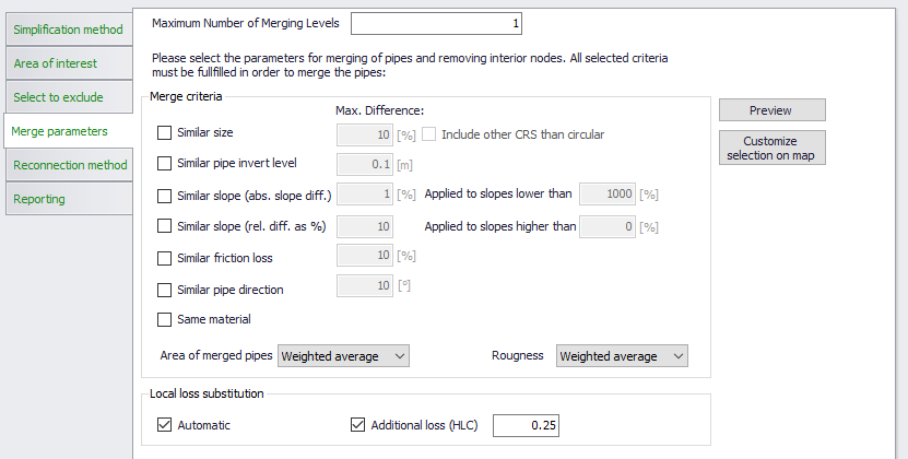
Figure: The CS Network "Merge parameters" page
"Merging" means joining two or more conduits along a network path into one conduit with equivalent hydraulic properties.
The orphan nodes remaining after the "merge" operation shall be removed. Also, any catchment or boundary condition attached to these nodes must be reconnected either to the remaining nodes or to the merged link.
General properties of merged conduits are:
- Slope is uniform and is calculated as a ratio between the connection level difference between the upstream and downstream node connection of the merged conduit and the total length of the merged conduits
- The merged conduit has the same shape of the cross section and the same size as calculated by the set criteria, along its entire length.
- If the sizes and types of standard conduits shapes (circular, rectangular, egg, O) or if the generic shape ID are identical for all included conduits in one stretch to be merged, then the merged conduit retains this size and type or the same generic shape ID.
- If the stretch of conduits to be merged contains conduits of different type and size in any combination, the merged conduit will be a circular pipe, with calculated equivalent diameter and Manning number.
- Conduits defined as "Natural channels" cannot be merged.
- The friction loss is defined with local data and is always calculated so that the conveyance of the merged conduit is identical to the weighted average conveyance.
- Horizontal layout of the conduit is unchanged, just the removed nodes are replaced by the link vertices.
- MUID of the merged conduit is constructed as follows:
MUID = concatenate( \<FromNode MUID> + "-->" + \<ToNode MUID>)
All activated merging criteria must be fulfilled simultaneously if the two conduits are to be merged.
The merging operation is performed in one or more levels. This is necessary as the set criteria may be fulfilled after the first level merging operation has been completed.
Before any user-specified merging criteria are evaluated, some general conditions must be fulfilled if two or more conduits are to be merged. These are:
- Included conduits must constitute a continuous flow path
AND
- Any of the internal nodes in the included stretch of pipes must be connected to only two conduits. I.e. any junction or splitter node with more than two links connected cannot be eliminated by merge operation.
In the following, workings of the specified criteria are described in detail:
Similar size
Two or more conduits will be merged because of "similar size" in the following case:
- For circular pipes if the difference in size (diameter) is smaller than the specified limits
- For circular, rectangular, egg, O shape, or any closed generic shape in any combination, if the difference in size (i.e. full-flowing conduit area) is smaller than specified limits
- Pipes with open generic shape with the same generic shape ID.
Similar pipe invert level
Two or more conduits will be merged because of "similar pipe invert level" in the following case:
- The pipe invert level difference for the two adjoining pipes is smaller than the specified limit
Same material
Two or more conduits will be merged because of "Same material" in the following case:
- The friction loss for the included pipes is based on pipe material
AND
- The pipe material is the same for all pipes included in the stretch
Similar friction loss
Two or more conduits will be merged because of "Similar friction loss" in the following case:
- The friction loss computation for the included pipes is based on the same formulation
AND
- The friction loss for the included pipes is based on pipe material or locally specified value for all pipes included in the stretch
AND
- The friction loss (Manning number or C-W coefficient) difference is within the specified limit
Similar slope (relative slope difference)
Two or more conduits will be merged because of "Similar slope (relative slope difference" in the following case:
- The slope of the included conduit is inside limit for the specified minimum and maximum slope
AND
- The relative difference of slope of the involved conduits is within the specified limit
Similar slope (absolute slope difference)
Two or more conduits will be merged because of "Similar slope (absolute slope difference" in the following case:
- The slope of the included conduit is inside limit for the specified minimum and maximum slope
AND
- The absolute difference of slope of the involved conduits is within the specified limit
Similar pipe direction
Two or more conduits will be merged because of "Similar pipe direction" in the following case:
- The angle (direction change) in degrees, between the last segment (i.e. the last vertex and the "TO" node) of the upstream link, and the first segment (i.e. "FROM" node to the first vertex) of the downstream link of the two conduits is inside the specified angle limit
Pipe merging methods
When a stretch of two or more conduits fulfils all the activated criteria for merging, they will be merged into one "equivalent" circular pipe, with the following properties:
- Upstream (invert) connection level is set to the upstream connection level of the upstream-most conduit in the stretch
- Downstream (invert) connection level is set to the downstream connection level of the downstream-most conduit in the stretch.
- Length is set to the sum of all conduits in the stretch. The upstream and downstream connection levels and the total pipe length determine the uniform slope of the merged "equivalent" pipe.
- Cross section type, size, and generic shape ID:
- If all conduits in the stretch to be merged have the same type and size, or the same generic shape ID, these properties are retained by the merged conduit.
- When conduits with different sizes and closed cross section types are included, the merged conduit type is set to be a circular pipe. Equivalent diameter for the merged conduit is calculated with one of the following methods, selected by the user:
- Weighted average cross section area. This is applicable for circular pipes, rectangular, egg, O-shape, generic shapes (closed) and any combination of the above. This method gives the equivalent pipe's volume equal to the volume of conduits included in the stretch. This is the default method.
- Max. cross section area (This is applicable for circular pipes, rectangular, egg, O-shape, generic shapes (closed) and any combination of the above): equivalent diameter for the merged pipe is calculated from the largest value of the cross section area included in the merged conduit.
- Min. cross section area (This is applicable for circular pipes, rectangular, egg, O-shape, generic shapes (closed) and any combination of the above). Eq. diameter for merged conduit is calculated from the smallest value of the cross section areas included in the merged conduit.
- The calculated equivalent diameter is rounded off to 1 cm.
- Friction loss (roughness): Equivalent roughness for the merged conduit is calculated by one of the following methods:
- The weighted average hydraulic grade. This method sets the equivalent roughness (Manning's number) of the merged conduit so that in full-flow conditions it generates the same friction loss as the original conduits before merging. This method is appropriate for the pipe stretches that are dominantly full flowing.
- The weighted average roughness. This method calculates the equivalent roughness (Manning's number) of the merged conduit as a weighted average for the included conduits. The weighting is based on the conduit lengths. This method is appropriate for the pipe stretches that at dominantly free-surface-flowing.
Local (minor) head loss substitution
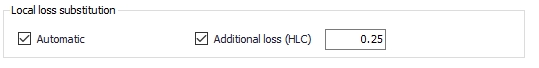
Figure: Activating local loss substitution
Some of nodes which get removed by the merging operation, may have included definition of local (minor) losses due to direction change, invert drop or flow contraction at the outlet. The loss of flow resistance due these head loss definitions in the removed nodes is (optionally) compensated by two methods:
- An automatic head loss substitution
- User-specified additional loss
Both methods are based on adjusting the merged pipe's equivalent Manning number, i.e. increasing the pipe's roughness., by the value that causes the additional friction loss along the merged pipe equivalent to the local head loss in the removed nodes, in conditions of full-flowing pipe.
The head loss substitution is activated by setting the checkmarks in the "Local loss substitution" box.
The head loss substitution is subject to the following:
- Nodes with method "No head losses" are excluded, i.e. no correction of Manning number in the merged pipe is needed
- For all nodes with local loss defined by the methods "Classic" or "Mean energy approach", a correction of Manning number in the merged pipe can be (optionally) applied:
- If the loss coeff. type is "Total HLC", the specified value is used directly in the calculation
- If the loss coeff. type is "Contraction HLC", the specified value is added to the calculated drop loss and direction change loss. The summed-up value represents the total HLC which is used in the calculation
- If the loss coeff. type is "Km", the specified value of Km is used to calculate contraction HLC. This is then added to the calculated drop loss and direction change loss. The summed-up value represents the total HLC which is used in the calculation.
A user-specified head loss is optionally specified as an alternative to the automatic substitution, or as a supplement to account for any local losses along the stretch of conduits to be merged, not included by the automatic method.
The user specified loss coefficient is used exactly in the same way as the losses substituted by increased friction loss by the automatic method.
Network merging parameters (WD Network)
Merging of pipes in WD networks is based on similar principles as described for CS network conduits.
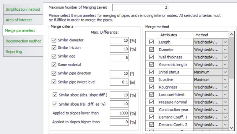
Figure: The WD Network "Merge Parameters" page
But, while all attributes for the CS network conduits are set or calculated by a predefined method, some attributes of WD pipes can be set or calculated by one of the following methods:
- Weighted average: the attribute is calculated as a weighted average
- Minimum
- Maximum
- Sum
General catchment merging parameters
General catchment parameters are subject to automatic merge operation that cannot be changed by the user. I.e. the user just needs to understand how does the merge operation act on the involved catchments.
Total geometric area is calculated as a geometric area of the merged catchment.
Total catchment area (user specified) for the merged catchment is calculated as follows:
- If none of the included catchments have user specified "Catchment area" defined, this attribute remains empty
- If all selected catchments have user specified "Catchment area" defined, the "Catchment area" of the merged catchment is calculated as a sum of all "Catchment area" values
- If only some of the selected catchments have user specified "Catchment area" defined, the "Catchment area" for the merged catchment is set as a sum of user-specified "Catchment area" values (where available) and the geometric areas (for catchments with undefined "Catchment area").
Person equivalents for the merged catchment is calculated as a sum of "Person equivalents" values for the selected catchments. If none of the selected catchments has "person equivalents" defined, this remains undefined also for the merged catchment.
Catchments merging parameters for hydrological models
For different hydrological models, the actual catchment merge operation must be configured by the user. This includes selecting the preferable automatic method for setting up the values of catchment merge parameters or setting up the values directly. This is achieved on the catchments "Merge parameters" pages, separately for each type of hydrological model.
The merge operation works for one runoff model type at a time, as specified on the "Area of interest" page. Accordingly, the page(s) containing the respective model parameters are made accessible.
Time-Area merge parameters
"Imperviousness" is calculated as a weighted average imperviousness, weighting based on the total catchment area. This is the default and only method, that cannot be changed.
Other time-area model parameters can be calculated or set according to the chosen method. The page containing time-area model parameters is accesible when merging catchments with runoff models "Time-Area (A)" and "Time-Area (A) + RDI".
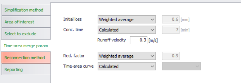
Figure: Time-Area merge parameters
The automatic calculation of model parameters is based on the local parameter values (where activated) or on the values from the applied parameter set for the actual catchments.
Time-area model parameters to be automatically set by the catchment merge operation are:
- Initial loss
Methods available for setting this parameter are:- Weighted average (default): Initial loss for the merged catchment is calculated as a weighted average initial loss, weighting based on the impervious catchments' area. If all included catchments have imperviousness zero, weighting is based on the catchments' total area.
- Minimum: Initial loss for the merged catchment is set to the lowest initial loss of the included catchments.
- Maximum: Initial loss for the merged catchment is set to the highest initial loss of the included catchments.
- User-specified: Initial loss for the merged catchment is set to the user-specified value.
- Concentration time
Methods available for setting this parameter are:- Calculated (default): Concentration time for the merged catchment is calculated as a product of the longest distance inside the merged catchment's polygon and the user-specified runoff velocity.
- Weighted average (default): Concentration time for the merged catchment is calculated as a weighted average concentration time, weighting based on the catchments' geometric area.
- Minimum: Concentration time for the merged catchment is set to the lowest concentration time of the included catchments.
- Maximum: Concentration time for the merged catchment is set to the highest concentration time of the included catchments.
- User-specified: Concentration time for the merged catchment is set to the user-specified value.
- Reduction factor
Methods available for setting this parameter are:- Weighted average (default): Reduction factor for the merged catchment is calculated as a weighted average reduction factor, weighting based on the impervious catchments' area. If all included catchments have imperviousness zero, weighting is based on the catchments' total area.
- Minimum: Reduction factor for the merged catchment is set to the Reduction factor of the included catchments.
- Maximum: Reduction factor for the merged catchment is set to the highest Reduction factor of the included catchments.
- User-specified: Reduction factor for the merged catchment is set to the user-specified value.
- Time-Area curve
Methods available for setting this parameter are:- Calculated (default): This method creates a new, 11-points time-area curve. The new curve's ordinates are calculated as weighted averages for the T-A curves of the included catchments. The weighting is based on the geometric catchments' area.
- User-specified: Time-area curve for the merged catchment is selected from the list of the available T-A curves.
Kinematic wave model merge parameters
"Contributing area" for all five surface types is calculated as a weighted average, weighting based on the total catchment area. This is the default and only method, that cannot be changed.
Other kinematic wave model parameters can be calculated or set according to the chosen method. The page containing kinematic wave model parameters is accesible when merging catchments with runoff models "Kinematic Wave (B)" and "Kinematic Wave (B) + RDI".
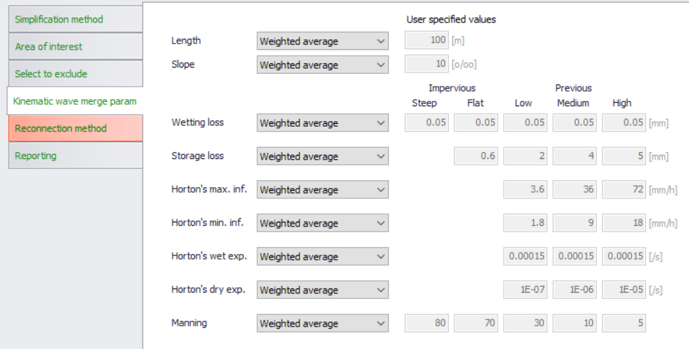
Figure: Kinematic wave model merge parameters
The automatic calculation of model parameters is based on the local parameter values (where activated) or on the values from the applied parameter set for the actual catchments.
Kinematic wave model parameters to be automatically set by the catchment merge operation are:
Catchment-wide parameters:
- Length (m)
- Slope (‰)
Parameters for various contributing surface types:
- Wetting loss (mm)
- Storage loss (mm)
- Horton's max. inf. Capacity (mm/h)
- Horton's min inf. Capacity (mm/h)
- Horton's wet weather exponent (/s)
- Horton's dry weather exponent (/s)
- Manning number
For all these parameters, methods available for setting the model parameter are:
- Weighted average (default): The catchment-wide parameters for the merged catchment are calculated as weighted averages, weighting based on catchments' geometric area. The parameters for contributing surfaces are calculated as weighted averages, weighting based on catchments' surfaces contributing areas.
- Minimum: Parameter for the merged catchment is set to the lowest value of the included catchments.
- Maximum: Parameter for the merged catchment is set to the highest value of the included catchments.
- User-specified: Parameter for the merged catchment is set to the user-specified value.
Linear reservoir model merge parameters
Effective area (%) (model C1) and Imperviousness (%) (Model C2) are calculated as a weighted average, weighting based on the total catchment area. This is the default and only method, that cannot be changed.
Other linear reservoir model parameters can be calculated or set according to the chosen method. The page containing linear reservoir model parameters is accessible when merging catchments with runoff models "Linear reservoir (C1)", "Linear reservoir (C2)", "Linear reservoir (C1)+RDI" and "Linear reservoir (C2) +RDI".
Depending on the chosen type of linear reservoir model (C1 or C2), the relevant attributes get activated or de-activated.
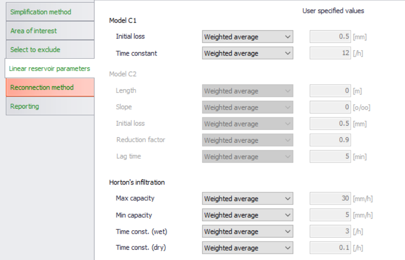
Figure: Linear reservoir model merge parameters
The automatic calculation of model parameters is based on the local parameter values (where activated) or on the values from the applied parameter set for the actual catchments.
The model parameters can be calculated or set by one of the following methods:
- Weighted average (default)
- Minimum: Parameter for the merged catchment is set to the lowest value of the included catchments.
- Maximum: Parameter for the merged catchment is set to the highest value of the included catchments.
- User-specified: Parameter for the merged catchment is set to the user-specified value.
The default method (weighted average) is different for various catchment-wide parameters, i.e. the weighting is based either on the contributing area or on the geometric area.
For the following parameters, weighting is based on "Effective area" (Model C1) and on "Imperviousness" (Model C2):
- Initial loss (C1)
- Initial loss (C2)
- Reduction factor (C2)
- Horton's Min capacity (C1 and C2)
- Horton's Max. capacity (C1 and C2)
- Horton's time constant (wet) (C1 and C2)
- Horton's time constant (dry) (C1 and C2)
For the following parameters, weighting is based on geometric areas:
- Time constant (C1)
- Length (C2)
- Slope (C2)
- Lag time (C2)
UHM model merge parameters
All parameters for the UHM model can be calculated or set according to the chosen method. The page containing UHM model parameters is accesible when merging catchments with runoff models "UHM" and "UHM+RDI".
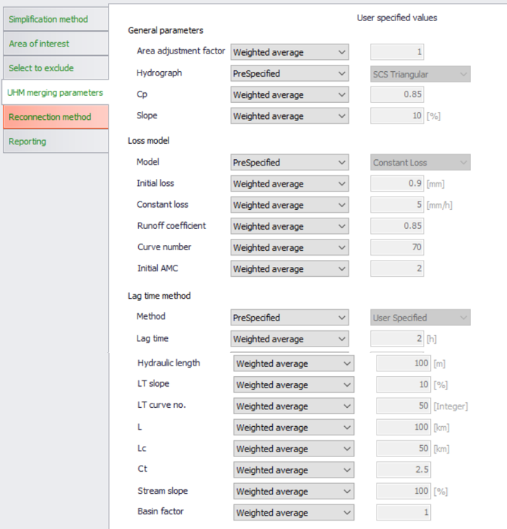
Figure: UHM model merge parameters
The UHM model's numeric parameters are calculated or set by one of the following methods:
- Weighted average, weighting based on the catchments' geometric area (default)
- Minimum: Parameter for the merged catchment is set to the lowest value of the included catchments.
- Maximum: Parameter for the merged catchment is set to the highest value of the included catchments.
- User-specified: Parameter for the merged catchment is set to the user-specified value.
Non-numeric parameters, which represent the choice among available options are:
- Hydrograph type
- Loss model type
- Lag time method
These are set as to one of the following options:
- Pre-specified (default): this option is valid and available when each of the selected catchments has the same option set in the original setup. I.e. the merged catchment gets the same setting of the parameter as the original catchments included in the merge operation.
- User-specified: this option can be actively chosen in any situation, but when the selected catchments have different parameter settings, it is the only option available. User must set the wanted value of the parameter.
RDI model merge parameters
Parameter "RDI area" (%) is calculated automatically as a weighted average, based on the geometrical catchment areas of the included catchments. This is default operation and cannot be changed by the user.
Parameter "Additional flow" (\(\text{m}^{3}/\text{s}\)) for the merged catchment is calculated as the sum of additional flows for the involved catchments (only with "additional flow" activated). This is default operation and cannot be changed by the user.
All other parameters for the RDI model can be calculated or set according to the chosen method.
The RDI parameters are presented in two pages (see below). The pages containing RDI model parameters are accesible when merging catchments with runoff models "RDI (solo)" and RDI model in any available combination with surface runoff models.
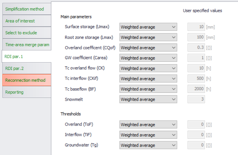
Figure: RDI model merge parameters (page 1)
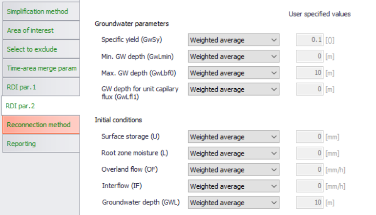
Figure: RDI model merge parameters (page 2)
All other parameters are calculated or set by one of the following methods:
- Weighted average (default)
- Minimum: Parameter for the merged catchment is set to the lowest value of the included catchments.
- Maximum: Parameter for the merged catchment is set to the highest value of the included catchments.
- User-specified: Parameter for the merged catchment is set to the user-specified value.
All parameters are weighted by the actual RDI area.
Weighting of the time constants CK, CKif and BF also includes the overland flow coefficient CQof , that accounts for the distribution of the RDI components.
Parameters for the surrogate model simplification
Applying the surrogate model simplification means replacing a prismatic conduit (e.g. a pipeline) by an orifice and a basin.
I.e., instead of a conduit between two nodes, an orifice is inserted. The orifice has a shape and size identical to the conduit's cross section.
The upstream node of the conduit is converted to a basin, and its volume is represented by the conduit's area-elevation curve, assuming a zero slope (i.e. conduit slope is not accounted for).
Normally, an outset for a surrogate model will be a model which is simplified by "Network trim" and "Conduit merge" methods, with the following remaining elements:
- Any important structures and nodes (basins, pumps, weirs, orifices, valves…)
- Merged conduits connecting model nodes, so that the main network layout and water transport ways are preserved. Distances between the remaining nodes (i.e. lengths of the remaining conduits) shall not be too long.
Ultimately, the final resulting surrogate model will be the model containing only important nodes and structures, including orifices and basin volumes representing major conduits. I.e. an ultimate surrogate model is a hydraulic model without any conduits.
While other types of structures remain in their original form, pumps will usually require modifications to "constant flow" pumps or similar, to avoid the pumping dynamics and therefore shortening simulation time step.
Accordingly, the surrogate simplification operation includes the following steps:
- Selected links are removed and replaced by additional volumes in upstream nodes and by orifice functions, according to specified parameters
- Any boundary conditions and catchments connected to the removed links are reconnected to the remaining nodes, according to the specified method.
Parameters that control the surrogate model simplification are found on the page "Surrogate parameters". This page is accessible when surrogate simplification category is chosen.
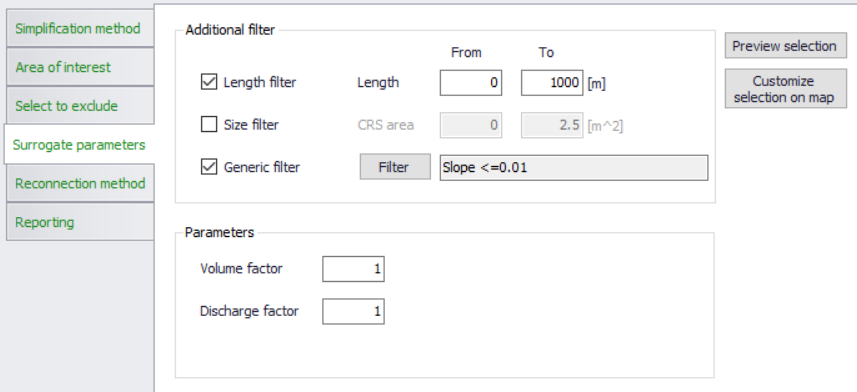
Figure: Surrogate model parameters
"Additional filter" focuses on easy selection of links to be converted to orifices. The filters activated here act on top of the selection defined by the "Area of interest" and "Select to exclude".
Length filter: allows to select the pipes within a specified range of length
Size filter: allows to select the pipes within a specified range of cross section area
Generic filter: allows for a specification of any generic filter
"Parameters" are the calibration factors for the two important parameters of the surrogate model:
- Volume factor: scales the volumes automatically included in the volume definition
- Discharge factor: Scales the automatically calculated discharge coefficient for the orifice.
Reconnection methods for network and surrogate simplification categories
In order to preserve the integrity and completeness of the loads to the simplified CS model, any catchments (i.e. runoff and catchment loads associated with these catchments) and network loads connected to the nodes and links removed from the model by any of the network simplification methods must be re-connected to the nodes or links remaining in the CS model.
Similarly, in order to preserve the integrity and completeness of the demands to the simplified WD model, any demands connected to the nodes and links removed from the model by any of the network simplification methods must be re-connected to the nodes or links remaining in the WD model.
This reconnection is done automatically, according to the specified reconnection method. The reconnection process is controlled from the page "Reconnection Method"
Reconnecting catchments (CS), loads (CS) and demands (WD) after network trimming
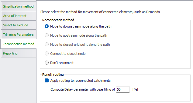
Figure: Reconnection methods for network trimming
The only reconnection method available for CS catchments, CS network loads and WD network demands left disconnected ("orphaned") by trimming is the connection to the downstream node along the path. E.g., if a dead-end pipe and its upstream node are removed, any CS catchment, CS network load or WD network demand originally attached to the upstream node or the pipe itself, in the simplified model will be attached to the pipe's downstream node - the one that remains in the model.
Alternatively, "Do not reconnect" would leave such CS catchments, CS network loads and WD network demands "orphaned", i.e. they would not contribute to the loads/demands of the simplified network.
Reconnecting the network loads in CS networks implies a loss of flow travel time, network volume and wave attenuation in the removed network. To account for this, a runoff routing can be activated during the CS network trimming operation. When the option 'Apply routing to reconnected catchments' is selected, the runoff routing (defined in the Catchment connections editor) will be activated. An attenuation of the runoff hydrograph will then be computed before it enters the trimmed network. This routing (attenuation) is computed using the Muskingum method, using the parameters defined in the Catchment connections editor. During the simplification process, the Delay parameter for each of these catchment connections will be updated, adding a flow time along all links trimmed downstream the catchment connection (i.e. between the original connection location and the new connection location after trimming). This flow time is computed using a flow velocity estimated with the Manning formula and with an assumption regarding the pipe filling, which is defined in the reconnection method settings.
Reconnecting CS catchments, CS loads and WD demands after network merging
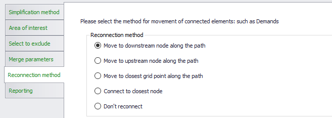
Figure: Reconnection methods for network merging
The reconnection methods available for "orphaned" CS catchments CS network loads and WD network demands by pipe merging are the following:
- Move to downstream node along path: This method reconnects any CS catchment, CS network load and WD network demand originally connected to the removed nodes and/or to the substituted conduits to the downstream node of the merged pipe.
- Move to upstream node along path: This method reconnects any CS catchment, CS network load and WD network demand originally connected to the removed nodes and/or to the substituted conduits to the upstream node of the merged pipe
- Move to closest grid point along the path: This method reconnects each CS catchment, CS network load and WD network demand originally connected to the any of the removed nodes and/or to any of the substituted conduits to the grid points of the merged pipe that are the closest to the original location of the connection.
- Connect to closest node: This method reconnects any CS catchment, CS network load and WD network demand originally connected to the any of the removed nodes and/or to any of the substituted conduits to the closest node in the network after merge operation.
Alternatively, "Do not reconnect" would leave such CS catchments, CS network loads and WD network demands "orphaned", i.e. they would not contribute to the loads/demands of the simplified network.
Reconnecting the CS network loads and CS catchments to the locations relatively far from the original connection location may imply change of flow time. In the current version, the simplification tool does not compensate for the lost flow time.
Reconnecting catchments and loads after Surrogate simplification
Reconnection options for this simplification type are similar as those available for pipe merge method.
The only difference is that (for obvious reasons) reconnection to grid points is not possible.
Reconnection methods for CS catchment merge simplification
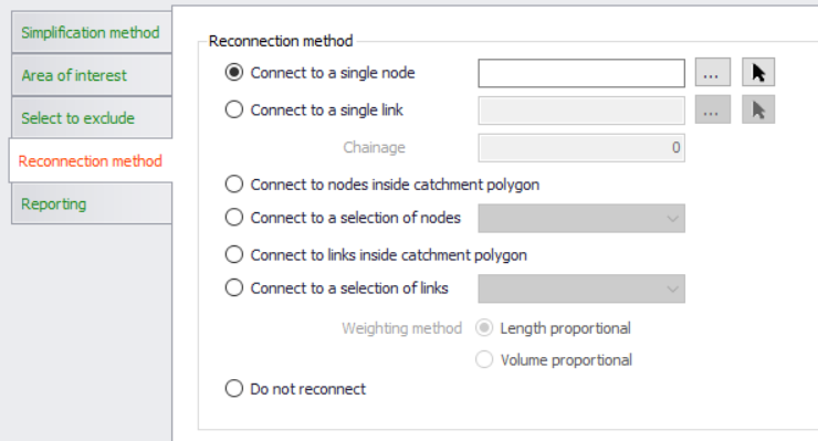
Figure: Reconnection methods for catchments merging
The reconnection methods available for merged CS catchments are the following:
- Connect to a single node: This method connects the merged CS catchment to the user-specified node.
The specified node must be of the same "Network type" as the current setting in "Area of interest". 100% of runoff and/or catchment discharges generated on the catchments included in the merge operation will flow into the specified node. All original catchment connections associated with the involved catchments are deleted. The new catchment connection is generated as type "Standard", "WW Total" or "SW Total, depending on the currently set "Network type". - Connect to a single pipe: This method connects the merged CS catchment to the user-specified link, to a grid point that is closest to the specified chainage (i.e. distance from the FROM node).
The link must be of the same "Network type" as the current setting in "Area of interest". 100% of runoff and/or catchment discharges generated on the catchments included in the merge operation will flow into the specified node. All original catchment connections associated with the involved catchments are deleted. The new catchment connection is generated as type "Standard", "WW Total" or "SW Total, depending on the currently set "Network type". - Connect to nodes inside the catchment polygon: This method connects the merged CS catchment to all eligible nodes inside the catchment polygon.
All original catchment connections related to the included catchments are deleted.
The runoff and catchment discharge are distributed to the nodes inside the merged catchment polygon with fractions corresponding to the area fractions obtained by Thiesen polygons method performed around the connection nodes. The sum of the fractions is 1 (i.e. 100%).
The new catchment connections are of the type "Combined partial", "WW partial" or "SW partial", depending on the actual "network type" currently set. - Connect to a selection of nodes: the merged CS catchment is connected to a set of nodes defined by a selection from the "Selection manager".
All original catchment connections related to the included catchments are deleted.
The runoff and catchment discharge are distributed to the selected nodes with fractions corresponding to the area fractions obtained by Thiesen polygons method performed around the selected nodes. The sum of the fraction is 1 (i.e. 100%).
The new catchment connections are of the type "Combined partial", "WW partial" or "SW partial", depending on the actual "network type" currently set. - Connect to links inside the catchment polygon: This method connects the merged CS catchment to all eligible links inside the catchment polygon.
"Eligible links" are those of the current "Network Type" and those that are completely inside the catchment polygon. I.e. links which cross the catchment boundary are not included.
The runoff and catchment discharge are distributed to the links inside the merged catchment polygon with fractions corresponding to one of the following options: - Length-proportional: the load is distributed proportionally to the links' length - Volume-proportional: the load is distributed proportionally to the links' volumes (calculated for full flow) - All original catchment connections related to the included catchments are deleted. - The new catchment connections are of the type "Combined partial", "WW partial" or "SW partial", depending on the actual "network type" currently set. - Connect to a selection of links: This method connects the merged CS catchment to the eligible links defined by a selection in the "Selection manager".
"Eligible links" are those of the current "Network Type".
The runoff and catchment discharge are distributed to the connections links with fractions corresponding to one of the following options: - Length-proportional: the load is distributed proportionally to the links' length - Volume-proportional: the load is distributed proportionally to the links' volumes (calculated for full flow) - All original catchment connections related to the included catchments are deleted. - The new catchment connections are of the type "Combined partial", "WW partial" or "SW partial", depending on the actual "network type" currently set.
Alternatively, "Do not reconnect" would leave the merged CS catchment disconnected.
Reconnecting the merged CS catchment using different reconnection options may imply the change of flow patterns. In the current version, the simplification tool does not compensate for these changes.
Saving the Configuration
Once the simplification method has been defined, it is possible to save the configuration into an *.XML configuration file.
This file can then be re-opened to be reused by clicking on the 'Open' button and browsing to the saved *.XML file.
Previewing results and generating report
By clicking on the button "Preview result" at the bottom of the simplification tool, the model features that are to be included in the specified simplification operation will be highlighted on the map and a summary with overview of the effects of the simplification will be generated in the "Reporting" page.
Example for a CS network Pipe merging simplification setup is shown in the two figures below.
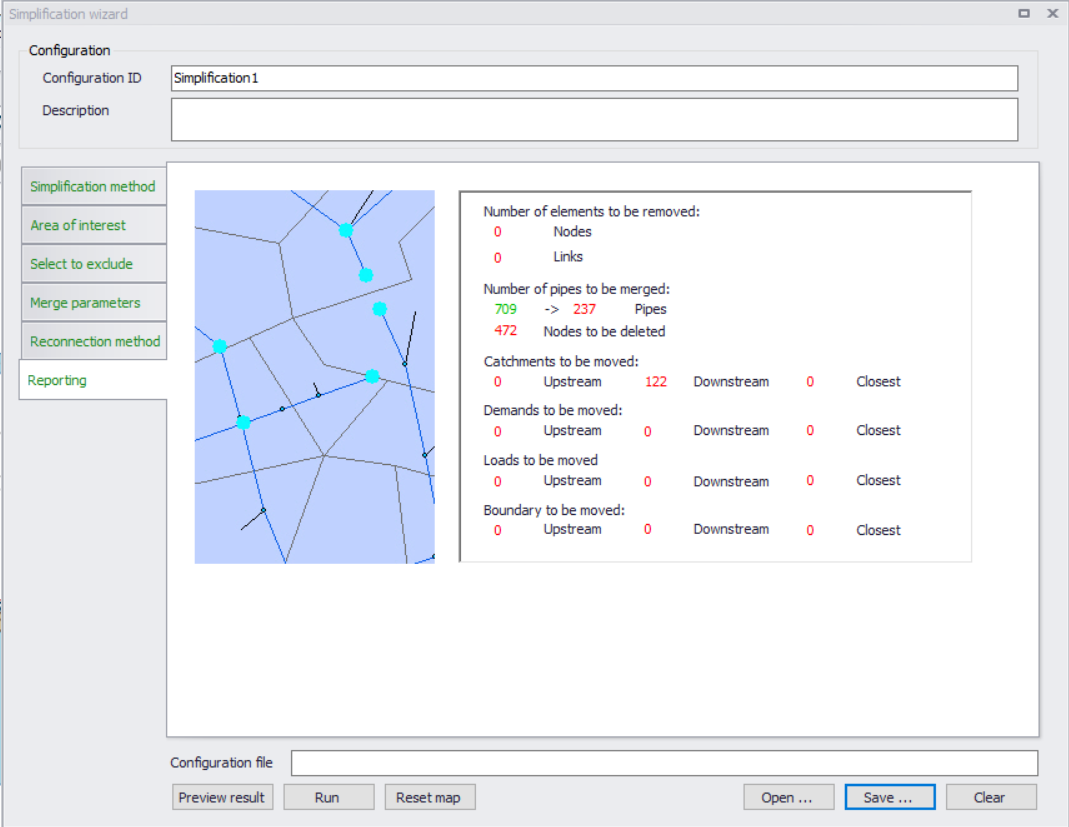
Figure: Summary report of simplification results
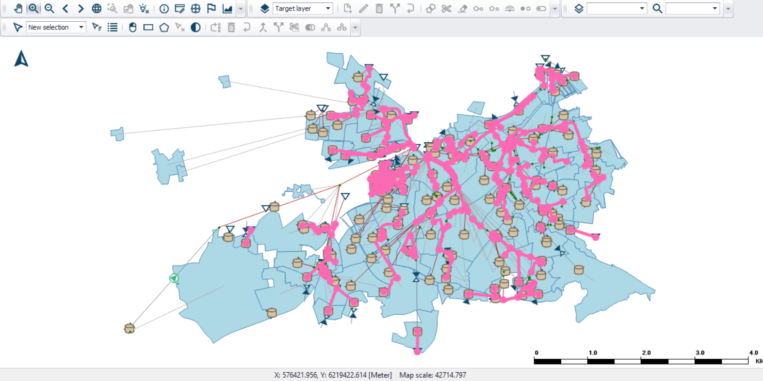
Figure: Highlighted model elements affected by the set pipe merge simplification
Executing the simplification
The actual simplification is executed by pressing the "Run" button. An example of a CS network before and after a simplification (pipe merging) operation is shown in the figure below.
An original model configuration can be recovered after any simplification operation by "Undo" function.
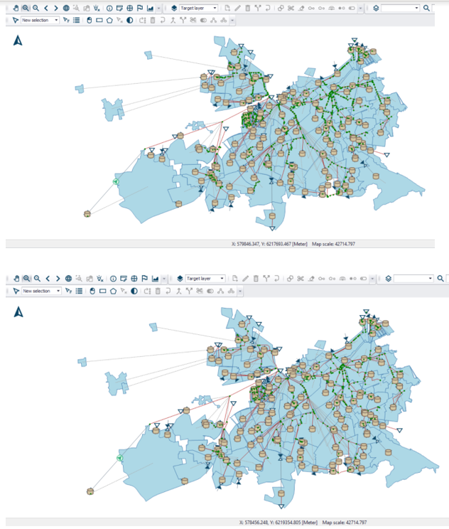
Figure: A CS network before (above) and after the pipe merge simplification. The original network has 1280 pipes, and the simplified network has 808 pipes.
Executing from command lines
The simplification tool can be configured and executed from the user interface as described in the previous chapters. However, there may be situations where it is required to automate the simplification without going through the related editors.
The MIKE+ executables enable you to execute some tools without opening the editor, through command lines. It is possible to run the simplification tool in this manner, assuming you have prepared the simplification configuration file beforehand in MIKE+.
Start by locating the MIKE+ executable named DHI.MIKEPlus.ToolShell.exe in the installation folder. From a command prompt, type the command below to access the list of supported tools, replacing the … characters by the actual path to the file:
The format of the command for executing a simplification configuration is:
Where [MIKE+ file] is the path to the .mupp or to the .sqlite file and [Configuration file] is the path to the .xml configuration file.