Pumps
Pumps are drainage system elements that lift water to higher elevations. The relation between a pump's flow rate and conditions at its end node is described by a pump curve. MIKE+ SWMM represents a pump as a link connecting two nodes, where the pump itself is placed at the upstream node.
The Pumps editor organizes the related input data into the following groups:
- Identification. General identification and connectivity information
- Pump Properties. Pump data
- Description. Optional descriptive information about the pump. Also includes an option for adding images of the structure.
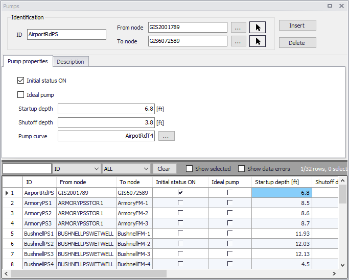
Figure: The SWMM Pumps editor
Identification
The identification groupbox holds information on the element ID and connectivity. Use the Insert or Delete buttons to add or remove records from the editor, respectively.
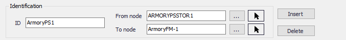
Figure: Pumps Identification groupbox
| Edit field | Description | Used or required by simulations | Field name in datastructure |
|---|---|---|---|
| ID | Id of the Pump | Yes | MUID |
| From Node | Location of Pump | Yes | |
| To Node | Receiving Node | Yes | |
| Description | |||
| Description | Descriptive information related to the structure | No | Description |
| Data Source | Reference to an external data source from which the record was imported | No | DataSource |
| Asset ID | Id in the asset management system | No | AssetName |
| Status | Status from a user- specified list in the Status Codes editor | No | Element_S |
| Network Type | Type of network i.e Stormwater, Combined or separate. The list of network types can be extended by the user. Network type can be specified for each element. | No | NetTypeNo |
| Tag | Optional label used to categorize or classify the pump | No | Tag |
Table: Edit fields in the Pumps Identification groupbox and Description tab (mss_Pump)
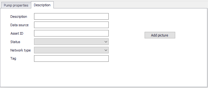
Figure: The Pumps Description tab
Pump Properties
Define essential pump properties on the Pump Properties tab page.
| Edit field | Description | Used or required by simulations | Field name in datastructure |
|---|---|---|---|
| Initial Status ON | Option to set initial status as ON | No | InitialStatusNo |
| Ideal Pump | Option to define the pump as “ideal” | No | IdealPumpNo |
| Startup Depth | Depth at the inlet node at which the pump turns on | Yes | StartupDepth |
| Shutoff Depth | Depth at the inlet node at which the pump shuts off | Yes | ShutoffDepth |
| Pump Curve ID | Reference to a tabular Pump curve in Curves and Relations | Yes | PumpCurveID |
Table: Edit fields in the Pump Properties tab (mss_Pump)
An ideal pump will have a flow rate equal to the inflow rate at the inlet node (From Node), and thus does not require a pump curve. The ideal pump must be the only outflow link from the inlet node.
A pump curve must be defined for each pump. Pump curves are defined in the Curves and Relations editor. The following pump curves types are supported:
- Pump Curve 1 (Volume-Flow). An off-line pump with a wet well where flow increases incrementally with wet well volume
- Pump Curve 2 (Depth-Flow). An in-line pump where flow increases incrementally with node depth
- Pump Curve 3 (Head-Flow). An in-line pump where flow varies continuously with head difference between the inlet and outlet nodes
- Pump Curve 4 (Depth-Flow). A variable speed in-line pump where flow varies continuously with node depth
- Pump Curve 5 (Head-Flow). A variable speed version of the Type 3 pump where the head versus flow curve shifts position when control rules change the pump's relative speed setting.
The on/off status of pumps may be controlled dynamically through user-defined control rules.