Lateral Snapping Tool
It can be difficult to exactly place nodes along the invert when digitizing an overland flow path whether it is along the gutter in a road or the invert of a waterway.
The Lateral Snapping tool, shown in the figure below, is used for automatically moving nodes and snapping them laterally to the lowest DEM value along a lateral snap alignment, which is shown in the second figure below. The length of the lateral snap alignment is specified in the tool.
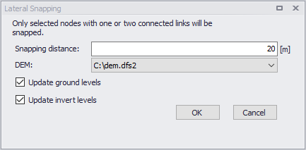
Figure: Lateral Snapping tool
When the selected node is connected to two links, the direction of the lateral snapping alignment will be created such that the internal angles between the upstream and downstream links are equal \(\theta_1 = \theta_2\), see figure below. If the selected node is only connected to one link, the direction of the lateral snapping alignment will be perpendicular to the link.
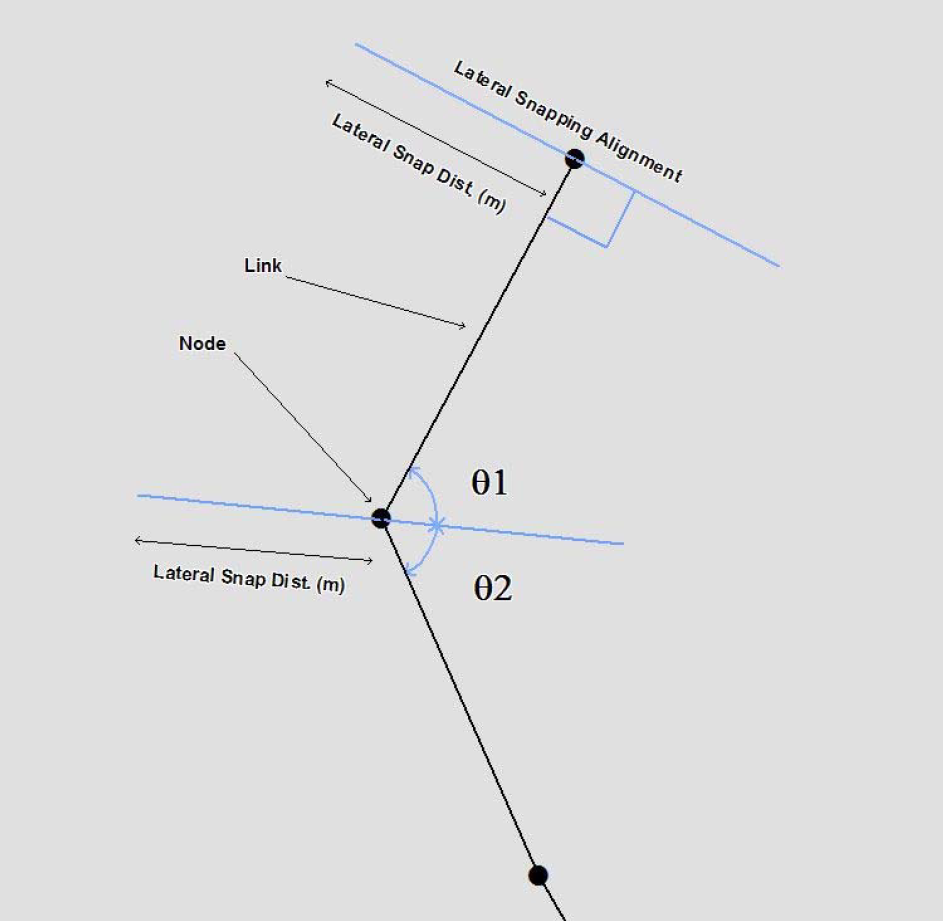
Figure: Lateral snapping concept
When nodes are moved to the lowest point, the tool can update either the ground level or the invert level according to the DEM. Note that the ground level should be updated for nodes belonging to the subsurface network and the invert level for nodes belonging to the overland flow network.
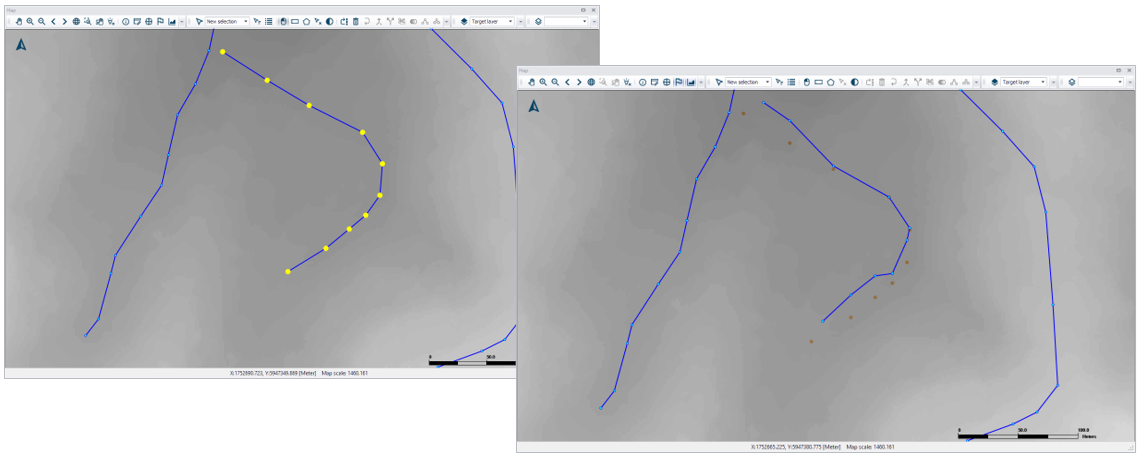
Figure: Example of nodes moved with the lateral snapping tool
The tool will only laterally snap selected nodes.