General Parameters
Three types of sediment transport analyses are supported by MIKE+ ST:
- Basic morphological analysis: in this type of analysis, the bed levels / sediment deposits are updated dynamically during the simulation (erosion/deposition) due to supply of sediments through the model's boundary condition and transport of sediments in the network. The basic mode offers simple and limited simulation options, primarily tailored for modelling the sediment transport in pipe networks.
- Advanced morphological analysis: this type simulates the same processes than the basic mode, but gives access to all sediment transport modelling options. This type is primarily designed for applications to river networks.
- Hydraulic effects only: this is an explicit method with disabled sediment transport processes. For this simulation type, the bed (sediments) levels are fixed during the simulation and controlled by the user-defined initial sediment depths, and any sediment boundary conditions is ignored.
With ‘Hydraulic effects only’ analyses, the bed level is fixed throughout the simulation and the only feed-backs from the sediment transport computations to the hydrodynamics are established via the reduced cross-section area and flow resistance (Manning number).
The flow resistance in a conduit with sediment deposits is calculated as a weighted average of the Manning number for the horizontal sediment bed and the wetted conduit walls. The Manning number of sediment deposits is controlled in the 'Pipes roughness' editor, and can be provided by the user or computed automatically based on the specified sediment fractions grain sizes.
No sediment is moved around in the system and any active sediment boundary condition is ignored. The only result items available for this type of analysis are: "Bed level", "Manning number" and "Bed shear stress".
This type of analysis is used to:
- investigate the hydraulic capacity in pipes with sediment deposits, i.e. document changes of hydraulic capacity and overflow volume and frequency due to sediment deposits and their removal;
- calculate and map bottom shear stress under representative hydraulic conditions. Result of this analysis may e.g. be used for planning of preventing maintenance (sediment removal) and identification of sedimentation-prone locations.
In morphological analyses (both basic and advanced), the sediment transport continuity equation is solved, based on the corresponding values of the hydrodynamic parameters (i.e. discharge, water levels, etc.). The feedback to the hydrodynamic module is established through dynamically changed flow area and flow resistance (Manning number).
The morphological ST model in MIKE+ allows for calculation of sediment transport for any number of specified sediment fractions, i.e. to perform the analysis for non-uniform sediments.
Basic morphological analysis
With 'Basic morphological analysis' type of simulations, the following additional settings must be defined in this editor.
Transport model
The transport of the coarse, non-cohesive fractions is modelled by one of four non-cohesive sediment transport formulae:
- Engelund - Hansen: The formula determines the total sediment transport directly. It has been derived from consideration of the work done by the flow on the sediment being transported. Originally, the formula was derived for a dune covered bed, but it was found applicable to the upper regimes (plane bed and anti-dunes) as well.
- Ackers - White: This formulae determines directly the total sediment transport. The formula is semi-empirical, based partly on dimensional analysis and partly on physical arguments.
- Engelund - Fredsøe - Deigaard: The formula calculates the total transport as the sum of the bed load transport and the suspended transport. The sediment transport is calculated from the skin friction, i.e. the shear stress acting on the surface of the bed. In this formula, it is possible to describe the development of sand dunes in pipes and hence include the resulting friction into the computations. The total bed resistance is then calculated as the sum of a contribution from the skin friction acting on the dune and an expansion loss behind the dune.
- van Rijn: In the van Rijn sediment transport formula, the sediment transport is divided into bed load and suspended load. The bed load is calculated from the saltation height, the particle velocity and the bed load concentration. The bed load computations follow the approach of Bagnold (1973), which assumes that the motion of the bed load particles is dominated by the gravity forces. When the bed shear velocity exceeds the fall velocity, the sediment is transported in suspension. The suspended load is calculated as the depth integration of the local concentration and flow velocity. The method uses the reference concentration computed from the bed load transport. The formula has been verified for particles in the range 200 - 2000 my-m. The verification based on 600 data sets, showed that 77% of the predicted bed load rates were within 0.5 and 2 times the observed values, van Rijn (1984a). The verification for the suspended load, using 800 data sets showed that 76% of the predicted values were within 0.5 and 2 times the observed values, van Rijn (1984b).
All non-cohesive fractions will be described using the selected transport model, in this type of analysis.
No general guidelines can be given for the preference of any one formulation over another, as this may be guided by the modeller's preference.
The implemented formulae demonstrate that the sediment transport is a highly non-linear function of the flow velocity: depending on the formulation, the sediment transport is proportional to the velocity raised to the power from 3 to 5. Obviously, a correct description of the hydrodynamics in the model setup is an essential prerequisite for a meaningful and accurate simulation of sediment transport.
Relative density
The density of all sediments in the model, relative to water. This density is assumed uniform throughout the entire network.
Porosity of deposits
The fraction of sediment deposits' volume filled with pores. This fraction is assumed uniform throughout the entire network.
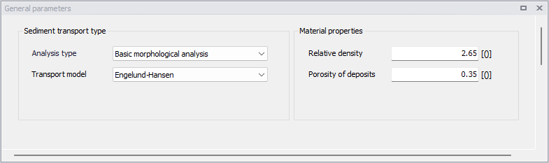
Figure: The 'General parameters' editor for basic morphological analyses
Advanced morphological analysis
With 'Advanced morphological analysis' type of simulations, the following additional settings must be defined in this editor.
Number of fractions
At least one fraction must be specified. The number of fractions can be controlled using this parameter, or by adding or removing records in the 'Sediment fractions' editor.
Include morphological update
When morphological update is not included in the simulation, the Sediment Transport module only computes a transport capacity, without any effect on the bed level. When morphological update is included, the bed level is continuously updated depending on local erosion and deposition, and therefore affecting the calculated hydrodynamic conditions. The method used to update the bed level is specified in the 'Bed parameter's menu.
Note
The morphological update affects the flow area, flow width and hydraulic radius values used in the hydrodynamic simulation, but it does not directly update the geometry of the physical cross sections. Therefore, the effect from the morphological update can be seen in the corresponding hydrodynamic result items (flow area, width, radius), but not on the shape of cross sections shown in the result files.
Maximum concentration allowed due to erosion
This parameter limits the erosion that can take place during a morphological time-step in such a way that the erosion cannot occur if it causes the sediment concentration to go above the specified maximum value. The limit applies to both bed load and suspended load.
For bed load it is applied in the form of translating the maximum concentration into a change in the sediment mass in the bed during the morphological time-step.
For suspended load the limit is used directly on the erosion function appearing on the right-hand side of the advection-dispersion equation.
The maximum concentration allowed due to erosion parameter is critical for morphological stability, but should be used with caution, as very low limits will suppress physics.
Skin friction model
The following options are available for the skin friction model:
- Total friction
- Law of the wall (full depth)
- aw of the wall (skin friction depth)
Use Egiazaroff hiding function
When multiple sediment fractions are simulated, the Egiazaroff hiding function can be applied.
Kinematic viscosity
The kinematic viscosity is used for calculation of the settling velocity for the sediment.
d90/d50
The d90/d50 value is required when modelling a single fraction.
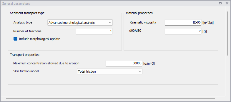
Figure: The 'General parameters' editor for advanced morphological analyses