Culverts
Culverts are structures that allow flows from one point to another through obstructions, such as roadways. Data on culverts are contained in the Culverts editor.
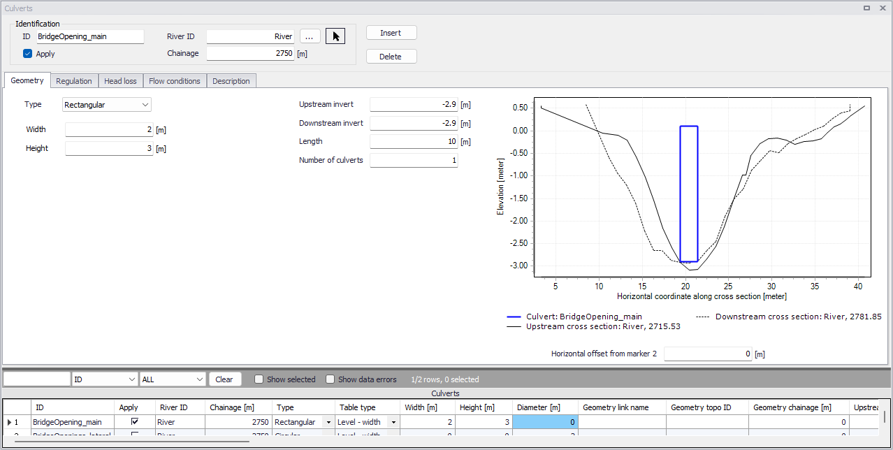
Figure: The Culverts editor accessed via the River Network setup group
Identification
The Identification group holds basic information on culverts.
ID
Unique string identification for the culvert.
River ID
The ID of the river branch where the culvert is located. The River ID is automatically registered is the culvert is defined via the Map. Use the button with an arrow, to select the location of the structure on the map: this will specify both the River ID and the Chainage of the structure.
Chainage
Chainage at which the culvert is located.
Apply
This check box allows the user to toggle the Active status of the culvert on and off. The simulations will omit all culverts that are not active.
Geometry
Geometric properties for the culvert are defined on the Geometry tab page of the Culverts editor.
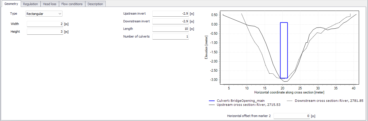
Figure: Geometry tab on the Culverts editor
Define properties such as:
Type
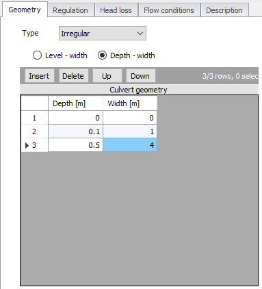
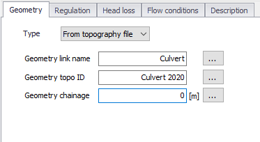
The type of cross sectional geometry for a culvert:
- Rectangular: The geometry is defined by width and height.
- Irregular: The geometry is defined using a level-width table or a depth-width table. Select the relevant table type and click on the Insert button to add rows to the table. Note that the values in the first column (level or depth) must be increasing.
- Circular: The geometry is specified by a diameter.
- From topography file: The culvert geometry is specified in the cross section editor. Select the Link Name (Branch ID), Topo ID, and Chainage of the cross section describing the structure’s geometry. If the cross section is an opened cross section, the structure will be an open culvert which is never submerged.
Upstream Invert
Invert level of the upstream end of the culvert.
Downstream Invert
Invert level of the downstream end of the culvert.
Length
Length of the culvert.
Number of Culverts
Number of parallel culverts.
Structure plot
To help ensuring that the geometry of the culvert is properly defined, the culvert's shape is shown and is compared to its upstream and downstream cross sections. On this plot, the horizontal axis shows the X-coordinates from the upstream cross section. The downstream cross section is then shifted so that its marker 2 is aligned with the marker 2 from the upstream cross section. The culvert shape is also centered around this marker 2, but can be moved horizontally using the value 'Horizontal offset from marker 2'.
Note on horizontal offset
This horizontal offset value is only used for the visualization purpose and has no impact on the simulation. Also note that the structure shape is always plotted in a symmetric manner although the actual structure may be asymmetric, and this doesn't affect the simulation neither as long as the flow area in the structure is correct.
Note on culvert's flow area
Since a culvert is defined as a structure causing a contraction loss, a friction loss (bend loss) and subsequently an expansion loss, the geometry of the culvert must be such that the cross sectional area at the inflow is less than the cross sectional area upstream of the culvert for all water levels. Similarly, the cross sectional area at the outflow end must be less than the cross sectional area immediately downstream of the culvert.
Regulation
Explicit regulation of flows through the structure may be set in the Regulation tab page of the Culverts editor.
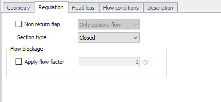
Figure: The Regulation tab on the Culverts editor
Non Return Flap
Activate this option to allow control of flow direction through the structure:
- Only Positive Flow: Only positive flow is allowed, i.e. whenever the water level downstream is higher than upstream, the flow through the structure will be zero.
- Only Negative Flow: Only negative flow is allowed, i.e. whenever the water level upstream is higher than downstream, the flow through the structure will be zero.
- No Flow: The flow through structures will always be zero regardless of upstream and downstream water levels.
Section Type
The culvert type must be specified as either open or closed for rectangular and irregular culverts. Circular culverts are closed, and culverts defined with a cross section definition are defined as open or closed in the Cross Sections editor/file.
Apply flow factor
When this option is active, the discharge computed through the culvert is multiplied by a flow factor. This factor's value is specified in the Flow factor field. The factor is a dimensionless factor, and a value of 1 means that no change is applied to the computed discharge. A value lower than 1 can typically be used to describe the reduction of the flow through the structure due to obstacles, like debris, restricting the flow area in the structure.
Head Loss
Define head loss parameters for the structure on the Head Loss tab page of the Culverts editor.
Head loss variables are included in the calculation of the flow direction-dependent energy loss for flow through hydraulic structures. They include:
- Manning's n: Manning bed resistance number along the culvert (for calculation of the friction loss through a structure with a certain length).
- Positive/Negative flow. Local head loss factors are defined for Inflow (entrance), Outflow (exit), Free overflow (correction coefficient), and Bends. Different loss factors can be applied depending on the flow direction across the structure.
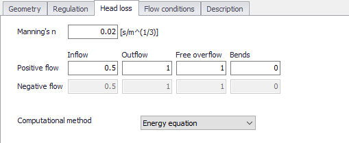
Figure: The Head Loss tab of the Culverts editor
Besides, a computational method must be selected. Two options are available:
- Energy equation: with this method, the flow through the structure is solved using the energy equation, in order to compute the discharge in the structure as a function of the head loss factors. The computed discharge is then applied at the calculation point. This is the preferred option in case there are big changes in cross sections before and after the structure, or if the flow area of the structure is much less than that of the river.
- Shallow water equation: with this method, the flow through the structure is solved adding a head loss term to the shallow water equation (Saint-Venant momentum equation), this term being a function of the head loss factors. With this method, the same equation is applied at structures' locations as at other regular calculation points (without structures). This ensures a continuity of the results between the upstream / downstream reaches and the structure, e.g. also including a bed friction between the upstream and downstream cross sections of the structure. Additionally, this method also enforces the use of velocity in upstream and downstream cross sections to compute the head loss, instead of using the velocity in the structure. This option is mainly designed for scenarios where the structure creates little or no head loss for low water levels, as e.g. for an overarching bridge. See the "Head loss mode" in the MIKE 1D reference manual, for more information.
Notes: When the flow through the structure becomes supercritical, the applied method is always the Energy equation. Besides, the 'Shallow water equation' method cannot be applied for structures located on rivers of type 'Structure link'. When several structures exist at the same location, if any of them uses the Shallow water equation method, then all other structures at the same location will also apply the same equation no matter the selected method in their properties.
Flow Conditions
Flow condition parameters through structures are shown in the Flow Conditions tab page of the editor.
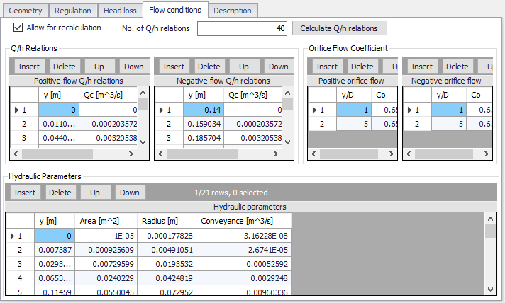
Figure: The Flow Conditions tab of the Culverts editor
Different hydraulic relations for the structure are automatically calculated by clicking on the ‘Calculate Q/h relations’ button once ‘No. of Q/h relations’ (i.e. data rows) has been specified.
Allow for Recalculation
Q/h relations can either be calculated automatically or entered/edited manually. If the Q/h relations have been modified manually, it is possible to prevent further changes to the values by unchecking ‘Allow for recalculation’. This will ensure that Q/h relations for this structure are not recalculated through the ‘Recalculate flow conditions’ function.
Q/h Relations
The Q/h relations are given as Q/y relations (where y is depth above the lowest of the Upstream and Downstream invert levels). The Q/y relations table also shows the type of flow occurring for the actual levels. Please note that the flow type definitions in the tables are only flow indicators derived from the Q/h table calculation, and these indicators are not directly impacting the calculation results. Hence, there will be no effect of changing these flow-type definitions on the calculation results.
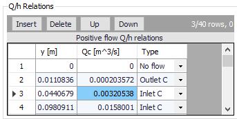
The possible flow types are:
- No Flow: No flow occurs at the first level (y = 0) and when the flap regulation flag prohibits flow in one direction.
- Inlet C: The flow at the inlet is critical.
- Outlet C: The flow at the outlet is critical. A backwater curve using a fine resolution is calculated to relate the discharge to the upstream water level in the river.
- Orifice: The flow at the culvert inlet has an orifice type formation.
- Full: The culvert is fully wet with a free discharge at the outlet.
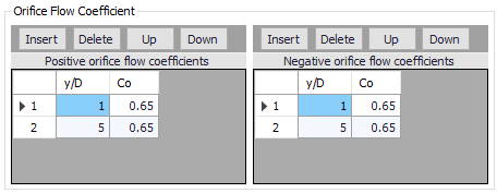
Orifice Flow Coefficients
Orifice type discharge is calculated based on the orifice coefficient tables shown in the this table. These coefficients can be edited, added or deleted, if needed. After editing the Orifice flow coefficients it is required to recalculate the Q/h relations using the ‘Calculate Q/h relations’ button.
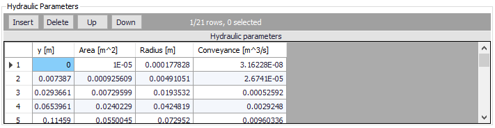
Hydraulic Parameters
The hydraulic parameters table shows level dependent parameters used in the calculation of Q/h relations. The hydraulic parameters are also used internally in the hydrodynamic engine when calculating the structure flow for other flow conditions than the free outflow. Hydraulic parameters include Flow Area, Hydraulic Radius, and Conveyance calculated for the level ‘y’ (depth above culvert invert).
To compute the Q/h relations, the nearest upstream and downstream cross sections are used. The cross sections must be located within a distance which is smaller than the user-defined maximum grid-spacing (‘Max dx’) for the branch in question. The Q/h relations cannot be calculated unless cross sections are defined.
Note
Note that Q/h relations must be re-calculated if any changes are made to the culvert and/or up/downstream cross sections. This is done by either pressing the ‘Calculate Q/h relations’ button on the editor for an individual structure or using the ‘Recalculate flow conditions’ function on the River Network menu ribbon.
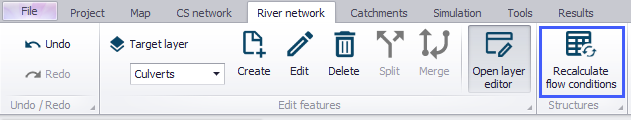
Figure: The Recalculate Flow Conditions function on the River Network menu ribbon
Description
Use the Description tab page to add free text descriptions for culverts. It offers options for providing asset and model management information, as well as attributes for quick model data query.
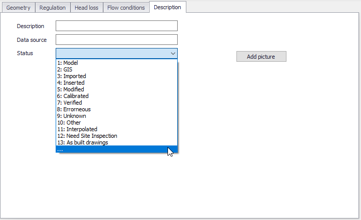
Figure: The Description tab on the Culverts editor
- Description: Free text description for the culvert.
- Data source: Free text describing data source for culvert data.
- Status: Project-defined status information that may be used for model build management or e.g. model data query. Pre-defined codes are contained in the Status Code editor which may be accessed via the ellipsis button from the Status dropdown menu (see figure above).
- Add picture: Option for adding images associated with the culvert structure.