Assignments
Assignment Structure
"Assignment" sets the value to one attribute in the target table. This implies that each assignment has a target attribute on the left side of "equals to" sign.
The right hand of the "equals to" sign may include one or more of the following:
- A simple constant
- Attribute value from a source table
- Attribute value from a LOOKUP table
- Value of a user-specified variable
- A value computed by an expression (including various functions and operators)
- A system-generated value
- A condition
Assignments are executed sequentially, as they appear in the editor. So, value of an attribute set in one assignment may be overwritten by another, subsequent assignment.
When importing data to a MIKE+ table, attributes without any assignment will be given the default (automatic) values from MIKE+. For example, when importing pipes geometries without assigning the pipes' MUIDs, each pipe will be given a default name like "Link_1".
Condition
Per default (i.e. with "condition" field empty), an assignment sets the target value unconditionally. Optionally, the assignment can be extended by a condition.
Creating Assignments
Creation of assignments is supported by the following:
- Automatic assignment (mapping)
- Add assignment and pick-up of target and source attributes from drop-down list
- Expression Editor, providing access to all source attributes, user-specified functions and operators
Auto Assignment
"Automap" button, located on the far right of the "Assignment" line, creates an assignment record for each target attribute name identical to source attribute name. I.e., if both source and target tables have identical structures, auto-assignment will create simple identity assignments for all attributes in these tables.
Repeated auto-assignment will re-write any existing assignments for the involved target attributes.
Insert Assignment
"Insert assignment" button inserts one empty assignment line above the currently active assignments in the current Section. In any case, user must select one target attribute from the drop-down list.
Depending on the situation, the next step may be the following:
- Select a source attribute from a dropdown list, thus creating a simple identity assignment, OR
- Open "Expression editor" (Press "fx" button in the "value" field on the current assignment line) and create an expression assignment
Optionally, use expression editor also to create a conditional clause.
Source Unit
Data in the source are often in different units than in the current MIKE+ project. Also, when exporting data from MIKE+ database, it is possible that the exported data should be in some different units than in MIKE+. For such cases, the tool supports automatic scaling of data.
When importing data to MIKE+, each assignment for a numerical "target" attribute, provides an information on unit for the attribute in the source table. Initially, this is set equal to the target (i.e. MIKE+) unit. In cases when the unit in MIKE+ and in the source are the same, no user action is needed: The value will be imported unchanged. If the source unit differs from MIKE+ unit, user must choose appropriate source unit from the drop-down list. If the actual source unit is not among the available units, the scaling factor for unit conversion must be specified directly as a multiplicator in the assignment expression.
Also, when the assignment statement involves two or more source attributes with different units, any unit inconsistency between the source and target must be handled explicitly by multiplication in the assignment statement.
Comment
This column can be used to add comments to any part of an import job, i.e. it is possible to comment a section and its main property lines, an assignment or an action. Comments will be saved with the import configuration, for later reuse.
Expression Editor
Expression editor supports creation of simple or complex assignment expressions, involving attributes, user-specified variables, functions and operators. Expression editor reduces the actual typing (hence the source of errors) to absolute minimum. Also, automatic expression validation is provided.
The left-hand side of the "equals to" sign of the expression is automatically provided. I.e. the user is expected to create only the right-hand side of the expression. This can be done either by direct typing, or by picking up the wanted variables, functions and operators from the respective drop-down lists. Typically, the process will involve both methods.
All variables in the expression should be embraced by square brackets ([]). This is a good practice, but not mandatory.
Strings should be embraced by double quotes ("").
The expression can be defined using the following controls.
"Variables" is a list including all attributes in the source table and any user-specified variable. A variable is included in the current expression by point & click. Square brackets are automatically provided.
"Functions" provides a list of available functions. A function is included in the current expression by point & click. Placeholders for the function's arguments are automatically provided.
"Operators" provide a list of available operators. An operator is included in the current expression by point & click.
The "Error list" reports "on-the-fly" any syntactic errors in the expression and provides advice on how to complete the expression.
"History" is a list of recently used expressions, available for reuse in the current assignment. Every new expression is automatically added to the history list. This allows for a very efficient reuse of similar assignments. "History" can be saved into a simple text file (*.TXT) and reloaded (Open) in a future import editing session.
The expression editor can be used in instances where the source data contains values in different formats to what is expected in MIKE+. For example, if the source data has node cover types specified in text format, while MIKE+ expects integers. The "fx" and "?" buttons in the assignment part of the "section" accesses the expression editor to state that if a condition is met ("?"), specify a value ("fx").
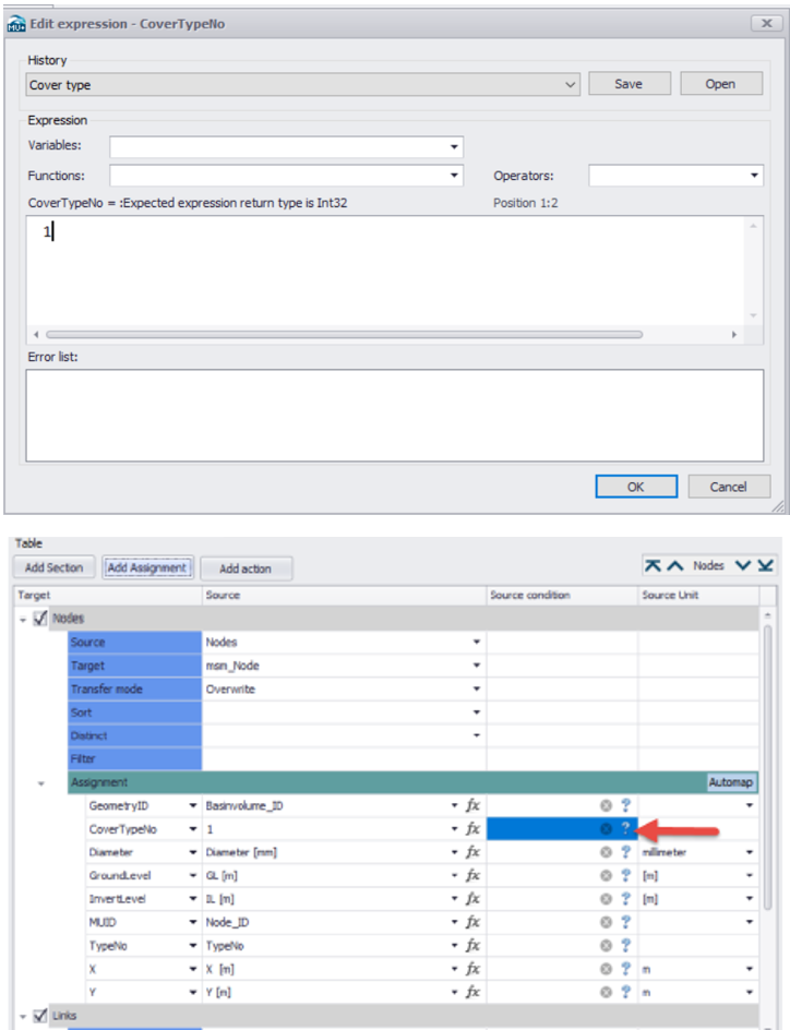
Figure: Expression editor is used for the easy creation of expressions with complex syntax. For example, if the "CoverTypeNo" is set as "Normal" in the source data, specify it as the number 1 in the target table.
A full reference on Expression editor's operators and functions is provided in chapter Expression Editor.
Assignments for CAD files
When MIKE+ data are exported to a CAD file, the following assignments can be used to control the properties of the CAD data:
- CAD_Text: text (label) for the exported feature. Only supported for point layers.
- CAD_LineTypeName: the line's name defined in the *.dwg template (MIKEPlusTemplate.dwg), e.g. Dash1.
- CAD_ColorIndex: the index of the color to be used in the CAD file. The index is an integer value. Can be used for point, text, polyline, polygon and block layers.
- CAD_ColorRGB: text string of RGB color representation. The divider is a comma (for example "128,0,255"). Can be used for point, text, polyline, polygon and block layers.
- CAD_LineWeight: line weight used by DWG files.
- CAD_Rotation: rotation of the element (typically used for text strings). The value is expressed in degrees.
- CAD_Height: height of the element (typically used for text strings). The value is expressed in the CAD "paper" unit.
- CAD_Block: name of the block. Some of the existing block names from the template file can be used. Block names available in the template are typically: Valve, Demand Allocation, Emitter, Check_valve, Load_point, Mouse_Basins, Mouse_Curb_Inlet, Mouse_Orifices, Mouse_Outlets, Mouse_Pumps, Mouse_Soakaway, Mouse_Valves, Mouse_Weirs, Reservoir, Swmm_Outlet, Tank, Turbine, Circle, Rectangle, Triangle.
- CAD_Block_ScaleX: scale of the block in the X direction.
- CAD_Block_ScaleY: scale of the block in the Y direction.
- CAD_Block_Height: block height. The value is expressed in the CAD “paper" unit.
- CAD_Block_Rotation: block rotation angle.
- CAD_FillColorIndex: index of the fill color, used by polygon layers.
- CAD_FillColorRGB: text string of RGB fill color representation, used by polygon layers.
These assignments must always be used in combination with a 'Geometry' assignment, used to export the shape on the map (point, polyline and polygon].
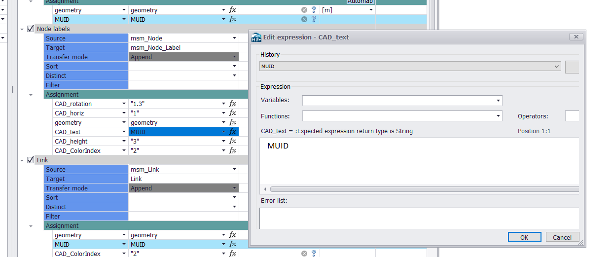
Figure: Creating assignments for CAD attributes
The source of these assignments must always be a text string. The text can be provided directly (to be specified in quotes, e.g. "1.25" where the decimal separator must be a point) or may be exported from a string attribute (e.g. MUID) or using a function 'ToString' to convert other input attributes to text.
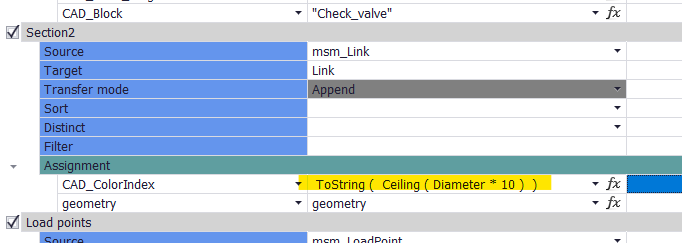
Figure: Creating an assignment controlling the color as a function of the diameter