Catchment Connections
In order to transfer the runoff generated on catchment surfaces into the collection network, the model must include information about the connection of the catchment outlet to the collection network. One or multiple catchments can be connected to one node, and a catchment can be connected to multiple nodes.
In order to use Catchments in the context of network modeling, they have to be connected to the network.
MIKE+ supports the connection of catchments to multiple locations (i.e. nodes or links), as well as separately allocating runoff and catchment discharges to multiple locations.
Catchment Connections Overview
An overview of relevant connections to a pipe network for catchments is available in the Catchments Editor Catchment Connections Overview Tab (Catchments\Catchments). It shows a table summarizing the connections of the catchment to the network model. The data dynamically link and refer to records in the Catchment Connections Editor (Catchments\Catchment Connections).
The summary table shows information on the following:
- Location. To which type of network element the catchment is connected, and the ID of the element.
- Catchment Runoff. Percentage of the Catchment Runoff from the catchment entering a location.
- Catchment Discharge. Percentage of the Catchment Discharge from the catchment entering a location.
- Action. Offers options for editing or adding connections for the active catchment:
- Edit. Opens the Catchment Connections Editor, wherein attributes for the existing catchment connection entry can be modified.
- Add connection. Adds a connection for the active catchment. The new connection is reflected in the overview table and the Catchment Connections Editor.
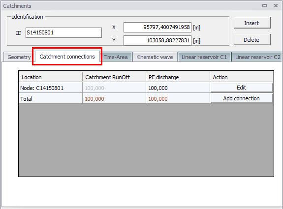
Figure: The Catchments Editor Catchment Connections Overview tab
Catchment Connections Editor
Connect catchments to the pipe network via the Catchment Connections Editor (Catchments|Catchment Connections).
The definition and management of catchment connections is supported both through Editors and by a set of graphical catchment connection tools.
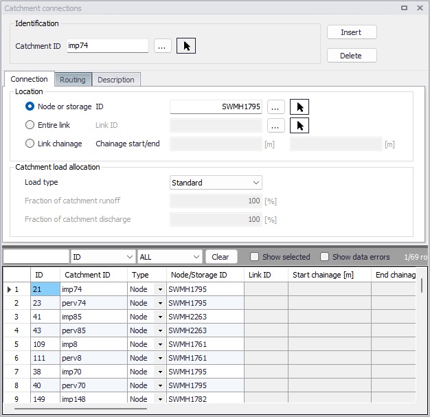
Figure: The Catchment Connections editor
Create catchment connections through the ‘Insert’ button. Multiple connections for a single catchment can be set up.
| Edit field | Description | Usage | Attribute Table Field |
|---|---|---|---|
| Catchment ID | Unique catchment identifier | Yes | CatchmentID |
| Location Type radio buttons | Specifies the type of network element to which the catchment is connected. Options are: Node Entire link, or Link chainage | Yes | TypeNo |
| Node ID | Unique identifier for the connected node | Yes, If Connection Type = Node | NodeID |
| Link ID | Unique identifier for the connected link | Yes, If Connection Type = Entire link or Link chainage | LinkID |
| Chainage start/end | Start and end chainages of the connected link | Yes, If Connection Type = Link chainage | StartChainage/EndCHainage |
| Load Type dropdown menu | Parameter that defines how the loads from the catchment are allocated to the pipe network for a connection. Options are: Standard, Wastewater Total, Stormwater Total, Combined Partial, Wastewater Partial, and Stormwater Partial. These different Load Types are further explained in the text below. | Yes | LoadTypeNo |
| Fraction of Catchment Runoff | Fraction of the catchment stormwater runoff to allocate for the connection | Optional, If Load Type = Combined Partial or Stormwater Partial | RRFraction |
| Fraction of Catchment Discharge | Fraction of the catchment discharge to allocate for the connection | Optional, If Load Type = Combined Partial and Wastewater Partial | PEFraction |
| Runoff routing method | Yes | RoutingTypeNo | |
| Delay parameter | Time for the runoff to travel to the network connection location. | Yes if Muskingum routing is chosen | RoutingDelay |
| Shape parameter | A dimensionless factor controlling the shape of the modified hydrograph. This factor depends on the shape of the modelled wedge storage and must be between 0 and 0.5. | Yes if Muskingum routing is chosen | RoutingShape |
| Description | Optional description of the catchment connection | No | Description |
Table: The Catchment Connections editor attributes (Table msm_CatchCon)
As a catchment can be the source of multiple load types (i.e. stormwater and wastewater), and can be connected to multiple network elements and network types, qualifying a load connection type into clear categories according to pipe network type and connection options is important. These Load Types are described in more detail below:
- Standard: This type of load connection applies to combined systems where all the catchment output is connected to a single location. This is the Default type, which corresponds to the MIKE URBAN Classic Single Node connection type.
- Wastewater Total: This type of load connection applies to fully separated systems, where the catchment is connected to a single location in the wastewater network.
- Stormwater Total: This type of load connection applies to fully separated systems where the catchment is connected to a single location in the stormwater network.
- Combined Partial: This type of load connection applies to combined systems where the catchment is connected to multiple locations in a combined network. This is the fully versatile connection type.
- Wastewater Partial: This type of connection applies to fully separated systems, where the catchment is connected to multiple locations in a wastewater network.
- Stormwater Partial: This type of connection applies to fully separated systems where the catchment is connected to multiple locations in a stormwater network.
The User's choice of Load Type affects the Catchment load allocation Editor fields and the internal data validation.
A facility for data validation checks that for each catchment in the Catchment Connections Editor, the sum of the fractions for Catchment Discharge (i.e. PEFraction) and Runoff Discharge (i.e.RRFraction) is close to 100 (99.9\<sum\<100.1).
For catchments where this sum is not found to be close to 100%, all specified connections will be reported as faulty and marked in red.
In the 'Routing' tab, it is possible to activate Muskingum routing along the catchment connection. When no runoff routing is applied, the runoff hydrograph entering the network matches the runoff hydrograph computed on the catchment. If Muskingum routing is applied, a change in hydrograph appearance occurs. This routing is designed to take into account the parts of the network between the catchment and the point of connection on the network, which are not included in the network model. This is especially relevant when the network is trimmed using the 'Network simplification' tool, in which case some parts of the network are removed and the neighboring catchments are reconnected to network locations further away, therefore neglecting parts of the flow path. The runoff routing in catchment connections can be activated automatically for reconnected catchments, while running the 'Network simplification' tool.
When the Muskingum method is selected, the two additional parameters below must also be specified:
- Delay parameter: time for the hydrograph to travel between the catchment and the connection location on the network. Its value may also be estimated as the observed travel time of the flood peak between the nodes.
- Shape parameter: a dimensionless factor controlling the shape of the modified hydrograph. This factor depends on the shape of the modelled wedge storage and must be between 0 and 0.5. If the shape parameter is set to zero, then the Muskingum routing will be very similar to linear reservoir routing.