Pipes and Canals
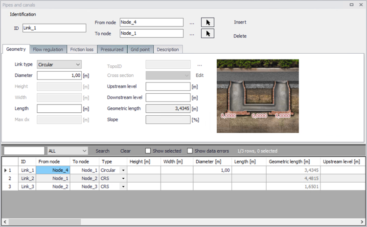
Figure: Pipes and Canals editor
A link (pipe or canal) is specified as a conduit between two nodes. A link is considered as either a straight line or a drawn polyline between two nodes and per default is assumed to connect the adjacent nodes at bottom levels.
Identification
General properties for pipes and canals are specified under the Identification group:
- ID: Unique identifier for a link.
- From node: ID of the connected node at the start of the link. This ID can be typed in manually, selected from a list using the corresponding ellipsis button or picked on the map using the arrow button.
- To node: ID of the connected node at the end of the link. This ID can be typed in manually, selected from a list using the corresponding ellipsis button or picked on the map using the arrow button.
In the computations the flow is considered positive when the water flows from the 'From node' to the 'To node'. Therefore, it is recommended to specify the nodes in the direction of predominant flows.
| Edit field | Description | Used or required by simulations | Field name in data structure |
|---|---|---|---|
| Link ID | A unique name for the node. Up to 40 characters (letters, numbers, blank spaces and underscore characters) | Yes | MUID |
| From node | Upstream Node | Yes | FromNodeID |
| To node | Downstream Node | Yes | ToNodeID |
| Apply | This check box allows to toggle the Active status of the link on and off. The simulations will omit all links that are not active. | Yes | Enabled |
Table: The edit fields in the Identification group (Table msm_Link)
Geometry
Depending on the selected type, a link may take the form of one of the 'standard' pipes (Circular, Rectangular, O Shaped, Egg-Shaped), or any closed or open generic shape (same cross section all along the pipe) or a natural channel (varying shape along the channel described with multiple cross sections).
Standard pipes are defined by diameter (or width and height for non-circular pipes).
For a pipe with a generic shape, the topography must be defined in the 'Generic shapes' editor, and the relevant shape ID must be selected in the 'Shape' list from the 'Pipes and canals' editor.
For a natural channel, the topography is defined by multiple cross sections, in the 'Cross sections' editor. In this cross sections editor, data are saved to an external cross sections file (*.xns11), and multiple 'Topo ID' can be defined for each natural channel. A Topo ID is a set of cross sections, containing all the cross sections along the natural channel. The possibility of storing multiple Topo IDs allows to define different topographies, for example before and after the construction of infrastructures in the channel. From the 'Pipes and canals' editor, the relevant Topo ID is selected in the corresponding field: pressing the '…' button will show the list of Topo IDs for the active natural channel, so it is important that the same natural channel ID is applied in both the 'Pipes and canals' editor and in the 'Cross sections' editor.
The length of a link is calculated from the shape of the line in MIKE+. The length is displayed in the 'Geometric length' field, and it is updated when the geometric reference is modified. If a user defined length is specified in the 'Length' field, this will overwrite the calculated one during simulation.
Per default, a link is assumed to connect the adjacent nodes at their bottom levels, which are shown for information in the fields 'UpLevel_C' and 'DwLevel_C', respectively.In case of a step-wise connection to the nodes (but not allowed below node bottom level), the elevations of both the upstream and downstream inverts of the link must be specified in the editable "'UpLevel"' and "'DwLevel"' fields.
| Edt field | Description | Used or required by simulations | Field name in data structure |
|---|---|---|---|
| Link type | Shape of pipe | Yes | TypeNo |
| Diameter | Nominel size of pipe (diameter of circular pipe, height of Egg-shape pipe and width for O-shaped) | Yes, if Link type = Circular, Egg-Shape and O-Shaped | Diameter |
| Width | Width of rectangular shape | Yes, if Link type = Rectangular | Width |
| Height | Height of rectangular shape | Yes, if Link type = Rectangular | Height |
| Shape | ID of the generic shape | Yes, if Link type = Generic shape | CrsID |
| Topo ID | ID of topography, i.e. ID of the set of cross-sections as defined in the Cross sections editor | Yes, if Link type = natural channel | TopographyID |
| Max Dx | Max distance between gridpoints | Yes, if Link type = natural channel | Maxdx |
| Length | User-defined length of link | Yes The geometric length will be used if left empty | Length |
| UpLevel | Upstream invert level of link | Yes | UpLevel |
| DwLevel | Downstream invert level of link | Yes | DwLevel |
Table: Geometry (Table msm_Link)
Flow Regulation
The 'Flow regulation' tab provides access to inserting a regulation in the selected link. This regulation does not require the Control module. The regulation can be either a maximum discharge as a function of the water level in a user specified node (Ctrl. Node A) or a maximum discharge as a function of the water level difference between two user specified nodes (Ctrl. Node A and Ctrl. Node B).
The option to apply a non-return valve to allow the water flowing in only one direction is also available.
| Edit field | Description | Used or required by simulations | Field name in data structures |
|---|---|---|---|
| Use flow regulation [Tickmark] | Allows the option to regulate flow to a given link | Yes, if flow regulation is chosen | FlowRegNo |
| Regulation type | Select the type of function desired to regulate the flow | Yes, if flow regulation is chosen | RegulaitonTypeNo |
| Function ID | Select the function that regulates the flow | Yes, if flow regulation is chosen | FunctionID |
| Non return valve [Tickmark] | Allows flow through the link in one direction only. | No | NonReturnNo |
Table: Flow regulation (Table msm_Link)
Wave Approximation
Wave approximation refers to the numerical solution and number of physical terms included in the Momentum equation applied in the Hydrodynamic simulation. For further details, please see the MIKE 1D reference manual.
By default, the wave approximation is selected for the entire CS network in the MIKE 1D engine configuration dialog. But it is possible to apply a different wave approximation for some pipes and canals. When the option 'Use specified local wave approximation' is selected, then it is possible to select the wave approximation for the current pipe / canal, which will take priority on the global wave approximation.
| Edit field | Description | Used or required by simulations | Field name in data structures |
|---|---|---|---|
| Use specified local wave approximation [Tickmark] | Replaces the global wave approximation type by a local type for the pipe | No | SpecLocalWaveNo |
| Wave approximation type | Selects the type of wave approximation desired for the current pipe | Yes, if specified local wave approximation is chosen | WaveApproximationTypeNo |
Table: Local wave approximation (Table msm_Link)
Note
When the 'Resistance formulation' is set to Colebrook-White or Hazen-Williams in the friction loss settings, then the wave approximation cannot be selected and is always set to 'FullyDynamicImplicitFriction'.
Friction losses
The resistance in the link can be computed using the following formulations:
- Manning (M): the resistance is characterized by a Manning (M) value.
- Manning (n): the resistance is characterized by a Manning (n) value.
- Colebrook-White: the resistance is characterized by an Equivalent roughness value.
- Hazen-Williams: the resistance is characterized by a Hazen-Williams coefficient.
Once the resistance formulation is selected, three definition types are available:
- Use material: select the material of the link from the list. The corresponding resistance value is shown on the left of the list for information. Specification of the different kinds of materials and their roughness coefficients is done through the 'Tables | Materials' editor. Changing the resistance value for a material affects all links defined with this material.
- Use local parameters: the resistance is defined specifically for the current link.
- Depth-dependent friction loss: the resistance value varies with an exponential low from the bottom to the top of the link.
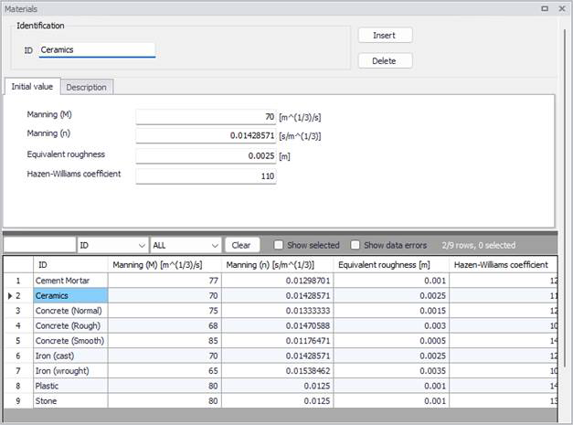
Figure: Materials editor
| Edit field | Description | Used or required by simulations | Field name in data structure |
|---|---|---|---|
| Material | Material of link | Yes | MaterialID |
| Resistance formulation | Formula for calculation of the friction loss (Manning (M), Manning (n), Colebrook White, Hazen-Williams) | Yes | FricTypeNo |
| Friction loss type (radio buttons) | Determines if roughness values are defined from the material, from a local value or using a depth-dependent law | Yes | FricNo |
| Manning | Manning roughness value | Yes, if ‘Manning (M)’ or ‘Manning (n)’ is chosen | Manning |
| Eq. roughness | Equivalent roughness | Yes, if ‘Colebrook White’ formulation is chosen | Rough |
| H-W coef | Hazen-Williams roughness coefficient | Yes, if ‘Hazen-Williams’ is chosen | HWCoef |
| Top | Depth-variable Manning number on Top | Yes, if depth-dependent friction is selected | ManTop |
| Bottom | Depth-variable Manning number on Bottom | Yes, if depth-dependent friction is selected | ManBott |
| Exponent | Yes, if depth-dependent friction is selected | ManExp |
Table: Hydraulic friction losses (Table msm_Link)
Pressurized
Pipes permanently running under pressure are specified by setting the tickmark in "Pressure main" in the "Pressurized" tab. Please refer to the MIKE1D Reference Manual (Pipe Flow) for further information on pressure main branches. This option is not supported for link types defined as Generic shapes or Natural channels.
The option to control the Preissmann slot ratio is also available.
| Edit field | Description | Used or required by simulations | Field name in data structures |
|---|---|---|---|
| Pressure main | Defines a link as pressure main. A link connected to a manhole or basin, can only constitute a pressure main if the manhole/basin is declared to be "tail node". Please refer to the MIKE1D Reference Manual (Pipe Flow) for further information on pressure mains. | No | PMApprNo |
| Use speci-fied Preiss-mann slot ratio | Enable the use of a user-defined Preissmann slot ratio | No | SlotNo |
| Slot ratio value | Rising main conversion factor | Yes, if 'Use speci-fied Preiss-mann slot ratio' is chosen | Slot |
Table: The edit fields in the Pressurized tab (Table msm_Link)
Grid point
Links will often be simulated with three calculation points: a h-point at the start and end of the link (where e.g. water level is computed) and one Q-point in the middle (where e.g. discharge and velocity are computed). When the link is long enough, intermediate calculation points are automatically added.
By activating the option 'Use specified grid points number', it is possible to force using a specific number of calculation points.
| Edit field | Description | Used or required by simulations | Field name in data structures |
|---|---|---|---|
| Use specified grid points number | Activates the use of a user-defined number of grid points | No | GridNo |
| Number of grid points | The specified number of grid points for the link | Yes, if 'Use specified grid points number' is chosen | Grid |
Table: The edit fields in the Grid points tab (Table msm_Link)
Description
The Description tab page is where free text descriptions for links data may be added. It offers options for providing asset and model data management, as well as attributes for quick model data query.
| Edit field | Description | Used or required by simulations | Field name in data structures |
|---|---|---|---|
| Asset ID | Reference to an ID used in external data sources | No | AssetName |
| Data source | Reference to an external data source (table ID) where the record has been imported from | No | DataSource |
| Element status | Data status for the entire record, serves for keeping track on the source of information | No | Element_S |
| Description | User's descriptive information related to the link | No | Description |
| Network type | Attributes the link to a certain type of network. Used in cases when two or more different networks are included in the same project | No | NetTypeNo |
Table: The edit fields in the Description tab (Table msm_Link)