Generate Cross Sections Tool
When overland flow paths or open channels are defined as MIKE+ links, a cross section needs to be assigned to each of these overland flow links. Often, a standard road profile will fulfil the modelling requirements. However, in other urban flood modelling situations, individual cross sections are required for open spaces, rural areas, park areas, etc.
The 'Generate cross sections' tool uses cross section alignments drawn in a line feature layer to extract cross sections from a DEM for links intersected by the alignments, see figure below. It generates cross sections for each link and sets the reference between the link and the generated cross section ID.
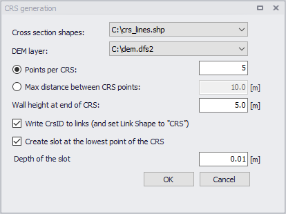
Figure: Cross Section Generation tool
Note
The DEM and cross section shapes need to be previously added. Use ‘Add layer…’ under the 'Layer and symbols' tree. The DEM layer needs to be a *.dfs2 file type (add layer ‘Raster layer’ type).
The manual digitalization of the cross section alignment lines can be guided by MIKE+ flood simulations results (1D/2D results) or an uncoupled 2D model where the precipitation is applied to the surface assuming that the subsurface network is completely full. Overland flood results can be used as a background layer in MIKE+. The only requirement for the digitized cross section lines is that they intersect the pertinent MIKE+ links. An example is shown in the figure below.
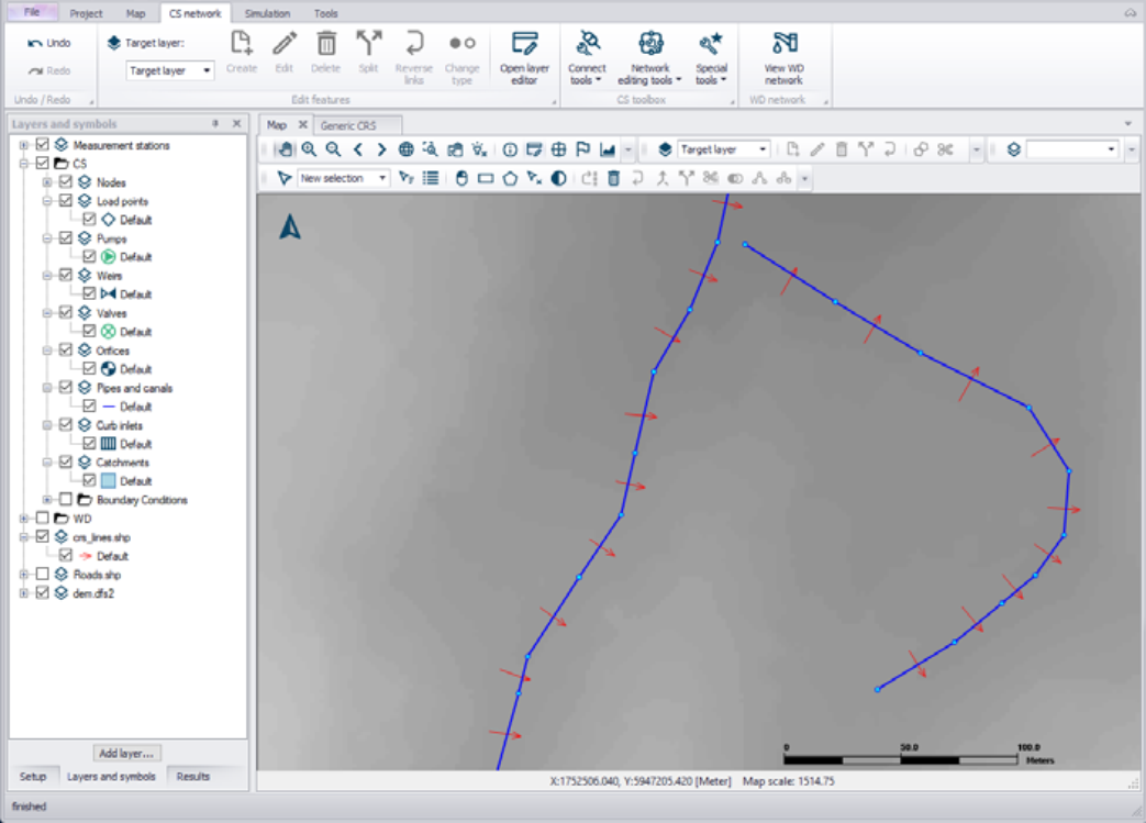
Figure: Example of defined cross section lines
Either the number of points or the maximum distance between points for a cross section can be specified. To fully capture the information from the DEM the resolution of the cross section should correlate to the resolution of the DEM.
The ID of the new cross section will be identical to the ID of the corresponding link. The cross section will be created with a width equal to the length of the corresponding cross section alignment line. The pertinent link will also be updated to use the new cross section by default, but this option can be disabled in the tool.
If the water level in a cross section rises above the defined cross section height, the simulation will stop by default. This is very common in stormwater models, so the tool allows for side-walls to be automatically added. Use a side-wall of 1 to 2 meters for an overland flow path such as a road, and 3 to 5 meters for waterways. The default value is set at 5m. Adding side-walls adds 2 points to the number of cross section points specified in the tool.
Another consideration is that if a cross section is very flat, too much numerical water will be generated when the link is running dry. Thus, a slot can automatically be inserted at the lowest point of the cross section.
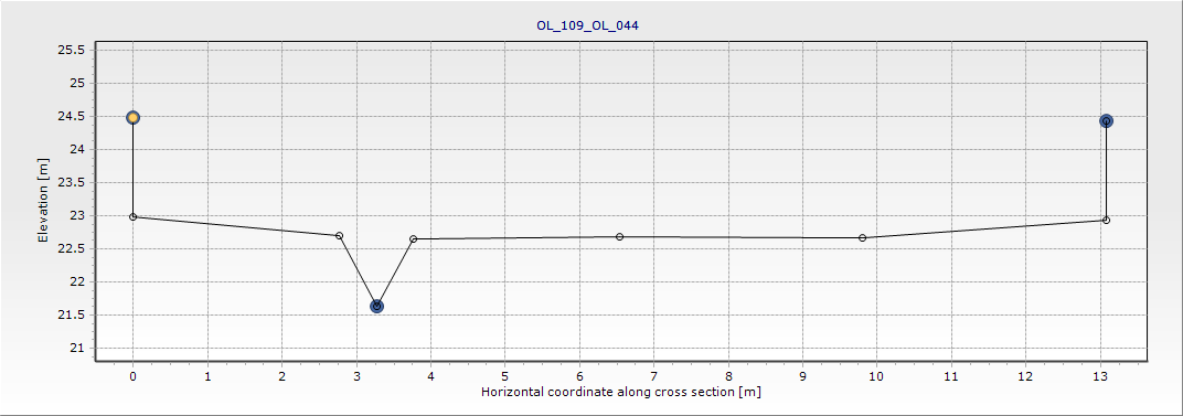
Figure: Example of cross section with inserted slot
The tool will generate cross sections for selected links or for all links intersecting alignments if no particular link is selected.
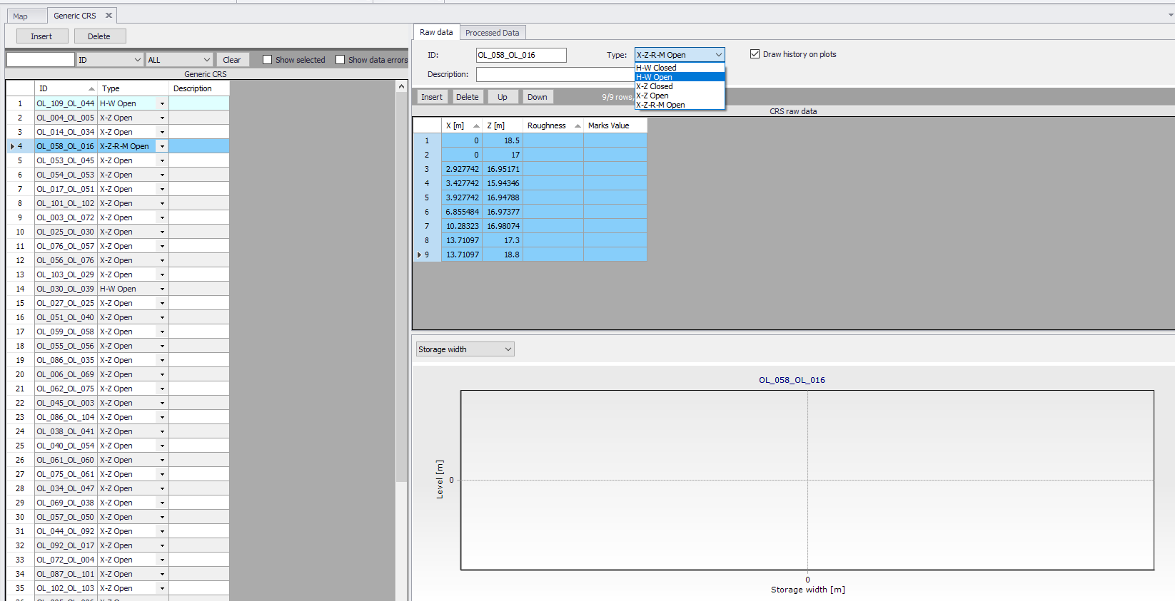
Figure: Automatic drawing cross section parameters