Actions
The action to be performed, when the condition associated to a rule is fulfilled, is defined in the Actions editor.
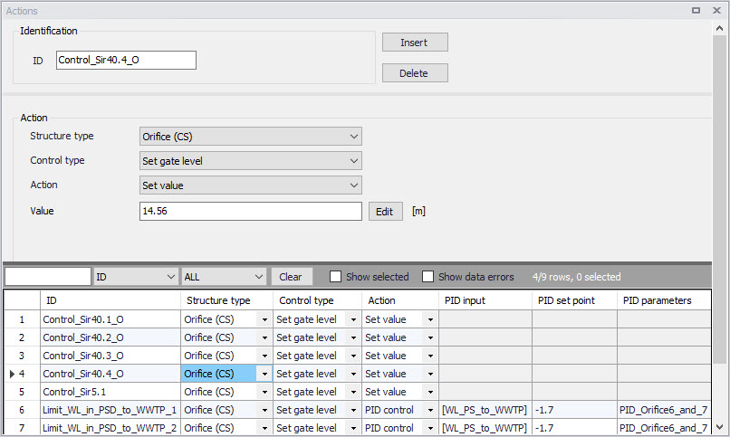
Figure: The Actions editor
Structure Type
This list controls the type of structure to which the action can apply. On a collection system network, actions can apply to:
- Pumps
- Weirs
- Valves
- Orifices.
On a river network, actions can apply to:
- Culverts
- Weirs
- Gates
- Direct discharges
- Dambreaks
- Pumps
- Bridges
- Tabulated structures.
Control Type
This field controls the variables to be regulated on the structure.
The available Control types are:
- For a pump (CS network):
- Set start level
- Set stop level
- Set flow
- Stop pump (taking the pump's deceleration time into account)
- Shutdown pump (halts the pump immediately)
- Resume pump (to be used after stopping or shutting down the pump)
- For a weir (CS network):
- Set weir crest level
- For a valve (CS network):
- Fully open
- Close
- Set valve opening
- For an orifice (CS network):
- Set weir crest level
- Set gate level
- Fully open
- Close
- Set gate minimum level
- Set gate maximum level
- For a culvert (river network):
- Set flow factor
- Set flow type
- For a weir (river network):
- Set weir crest level
- Set weir coefficient
- Set flow factor
- Set flow type
- For a gate (river network):
- Set gate level
- Fully open
- Close
- Set gate minimum level
- Set gate maximum level
- Apply natural flow
- Set flow factor
- For a direct discharge (river network):
- Fully open
- Close
- Set flow
- Set minimum flow
- Set maximum flow
- Apply natural flow
- For a dambreak (river network):
- Set flow factor
- Start breach (must be combined with a ‘Wait’ action)
- Wait (no operation: to be applied until the breach is started)
- Set flow type
- For a pump (river network):
- Set flow
- Apply natural flow
- Stop pump
- Shutdown pump
- Resume pump
- Set start level
- Set stop level
- For a bridge (river network):
- Set flow factor
- Set flow type
- For a tabulated structure (river network):
- Set flow factor
- Set flow type
When the control type applies to a variable specified in the structure editor, the value from the action will overwrite the value from the structure editor during the simulation. For example, when controlling the start level of a pump, the 'Start level' value specified in the Pumps editor is replaced by the value from the actions, when the pump is controlled.
When the control type is 'Apply natural flow', the structure is ignored and the flow is computed as in a natural channel.
Note
For a pump, it is not allowed to control simultaneously its flow and its Start / Stop levels.
Action
This controls the type of action which is performed. The following options are available:
- Keep unchanged: the controlled parameter (e.g. the gate position or the flow) remains unchanged, i.e. equal to its previous value.
- Set value: the specified value in the 'Value' field is an absolute value (e.g. level for a gate position or discharge for a flow).
- Set relative change: the specified value is a relative change from the previous state.
- Set value from time series: the time-varying absolute value is specified in a time series file.
- Set value from table: the absolute value is specified in a table, containing the relationship between an input variable and the desired value (output). The table is defined in the 'Curves and relations' editor (with curve type 'Generic control rule'), or in the 'Two-dimensional tables' editor (with type 'Time varying control rule') if this relationship varies in time.
- Set relative change from table: the relative change is specified in a table, containing the relationship between an input variable and the desired value (output). The table is defined in the 'Curves and relations' editor.
- Set value from 2D generic table: the absolute value is specified in a table, containing the relationship between two input variables and the desired value (output). The table is defined in the 'Two-dimensional tables' editor (with type 'Generic control rule'). The corresponding input variables are defined as expressions in the 'Table's X input' and 'Table's Y input' fields. Note that the unit of the output values from the table depends on the control type defined in the 'Actions' editor and is the same as what would apply with the action type 'Set value'.
- PID control: the value of the controlled parameter is assessed indirectly, by minimizing the deviation from the expected value.
- Apply natural flow: the structure is ignored and the flow is computed as in a natural channel.
- Apply structure flow: the action triggers the use of the regular energy loss calculation in a structure. It is meant to enable the calculation of the flow through the structure, when combined with the 'Apply natural flow' action.
Value
The absolute value or relative change to be applied. The value can either be a simple numeric value or derived from an expression. The 'Edit' button may be used to specify an expression.
File name
The path to the time series containing the values to be applied.
Table ID
The table ID, as specified in the 'Curves and relations' editor, to be used to define the value. The tabular data shall represent the functional relation between the input (e.g. input sensor reading or a combination of two sensors) and the return value. The tabulated values are linearly interpolated between defined values. The selected table may also be selected from the tables listed in the 'Two-dimensional tables' editor, if the table should vary over time. With this type of table, the relationship between the input variable and the return value (output) is a function of time. If the input value obtained during the simulation is smaller than the smallest input value specified in the table, then the column related to the smallest input value is used. If the input value obtained during the simulation is greater than the greatest input value specified in the table, then the column related to the greatest input value is used. The table may also be selected from the 'Two-dimensional tables' editor if the table should vary as a function of two input variables (table type 'Generic control rule').
Table's input
Indicates the variable used as input in the table. The 'Edit' button may be used to select e.g. a sensor.
Values specified as yearly variation
This may be used to apply the same yearly pattern to multiple years. When selected, values will be interpolated between the first and the last values specified within the year, and between the last and the first values. When unselected, if the time span of the table does not cover the whole simulation period, the first values of the table will be used for earlier dates and times, and the last values of the table will be used for later dates and times. Only available when using a two-dimensional table.
PID set point source
This controls the type of set point for the PID control. The following options are available:
- Expression: the specified value in the 'PID set point' field is an absolute value defined by an expression
- Time series: the time-varying absolute value of the set point is specified in a time series.
- Table: the absolute value is specified in a table, containing the relationship between an input variable defined by the Table input and the output which is identical to the desired setpoint
PID input
For a PID action, the Input parameter is the parameter being evaluated against the setpoint (i.e. target) value at the setpoint for the controlled device.
The Expression editor may be used to define the Input. Note that a Double data type is expected from the evaluation of the input expression.
The input may involve two sensors e.g. if the flow is regulated as a function of the difference between two level sensor values.
PID setpoint
The setpoint value (i.e. target) for a PID control action.
When the 'PID set point source' is set to use an expression, the Expression editor may be used to define the Setpoint (constant value or functional relation). Note that a Double data type is expected from the evaluation of the setpoint expression. It is also expected that the expression of the setpoint returns a result in the same unit as the 'Input'.
When a time series is used as 'PID set point source', it holds the path to the time series file.
When the 'PID set point source' is set to use a table, the field holds the table ID, as specified in the 'Curves and relations' editor. The tabular data shall represent the functional relation between the input (e.g. input sensor reading or a combination of two sensors) and the return value (setpoint or setting). The tabulated values are linearly interpolated between defined values.
PID parameters
The set of PID parameters used in the PID control. These sets are defined in the PID parameters editor.
Indicates the variable or expression used as input in the table for PID set point source. The 'Edit' button may be used to select e.g. a sensor or specify an expression.
Set point scale / Scale factor
The set point or time series will be multiplied by this factor. The scale can either be a constant value or an expression. The 'Edit' button may be used to specify an expression.
The figure below shows an example Action setup that is used for a PID-controlled orifice.
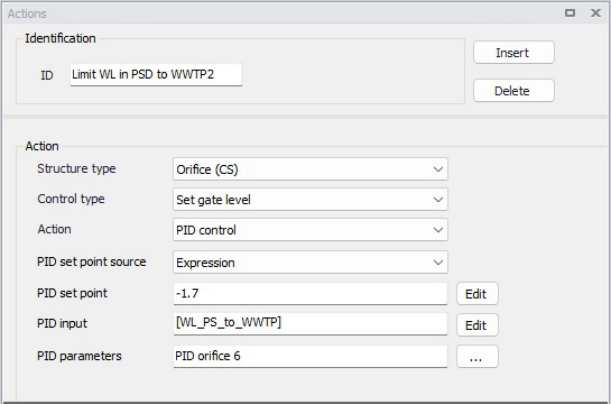
Figure: Example of PID Action
In this example, the orifice gate level shall be modified for controlling the water level at setpoint location [WL_PS_to_WWTP], where the expected water level is -1.7 m.
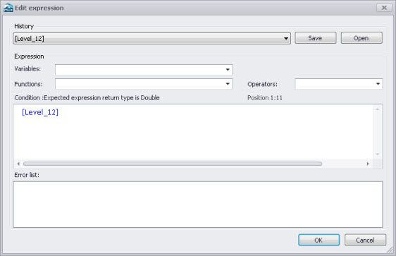
Figure: Example Input expression in Expression editor
Initially, one may start with the Variables dropdown menu in the Expression editor when building expressions for Input. The Variables dropdown offers predefined variables, such as Sensors.
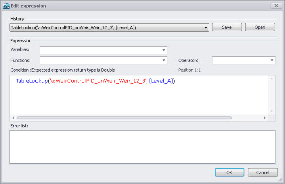
Figure: Example Setpoint expression in Expression editor
Functions and Operators may also be used to define more complex expressions for both Input (e.g. difference between 2 sensors) and Setpoint (e.g. TableLookup).
Note
The expressions must be written with the syntax from C# programming language. Therefore, the few rules below should apply:
- An equality check is written ==. For example, the condition for verifying if the simulation time is in August is: Month(SimulationTime()) == 8
- The AND condition is written &&, whereas OR is written ||. This is shown in the 'Operators' drop-down list, but the text AND and OR should not be used in the condition.
- A path to file must be written with double \ For example, if a condition looks up the time series C:\Data\TS.dfs0, the file path in the function must be written C:\Data\TS.dfs0.
- The decimal separator must always be a point.