2D Culverts
A typically embedded structure that allows water to flow from an open channel through an obstruction such as a road, railroad, wall, etc. can be represented by a 2D culvert in MIKE+. The result is that a head loss is applied between two 2D cells, a line of cells or two cross-sectional lines of 2D cells.
Culvert Types
Two types of culverts are available:
- Short Culvert
- Long Culvert.
Short Culvert
A short culvert is defined as a cross section where the total discharge across the cross section is calculated using empirical formulas and distributed along the cross section. In the numerical calculations the cross section is defined as a section of element faces which are treated as an internal discharge boundary.
The culvert points represent a cross section of the channel. Element faces from the mesh or grid are then selected based on this cross section: an element face is included in the culvert's section when the line between its two neighboring elements' centres crosses one of the cross section segments (see Location of structures in 2D domain for more details). To identify the exact faces where the culvert's calculation applies, the 2D log file can be interrogated as it will list all element faces selected along the cross section.
During the model initialisation period, the engine will look at the ground level in the cells / mesh elements on both sides of the selected element faces, and check if they are greater than the culvert invert. If these ground levels are higher than the culvert invert level, then an error message will be thrown. Therefore, it is important to make sure that the ground levels (defined in the 2D domain file) across the culvert are less than or equal to the respective culvert upstream and downstream invert levels.
The short culvert module was designed for applications where the length of the culvert is similar or smaller than the cell / element size of the 2D domain. Thus when using a culvert in a 2D domain with a fine resolution, it is important to take care with schematization, as described in the example below. Culverts that are much longer than the cell/element size can instead be modelled as a long culvert.
Example of a short culvert setup:
There are two images in the figure below illustrating a case with a stream running south to north and a road bisecting the stream. The image on the left shows the raw data, where the road is described in the topography and where the black line represents the culvert's cross section location. This setup does not work for a short culvert, because the topography in the cells downstream the culvert's cross section is higher than the culvert invert level.
The right image illustrates the grid modified in order to fit the requirements for using a short culvert. The water level upstream of the culvert is calculated from cells 1 and 2 and the downstream water level calculated from cells 3 and 4. The flow through the culvert will be computed using the resulting upstream and downstream water levels, and the culvert's geometry.
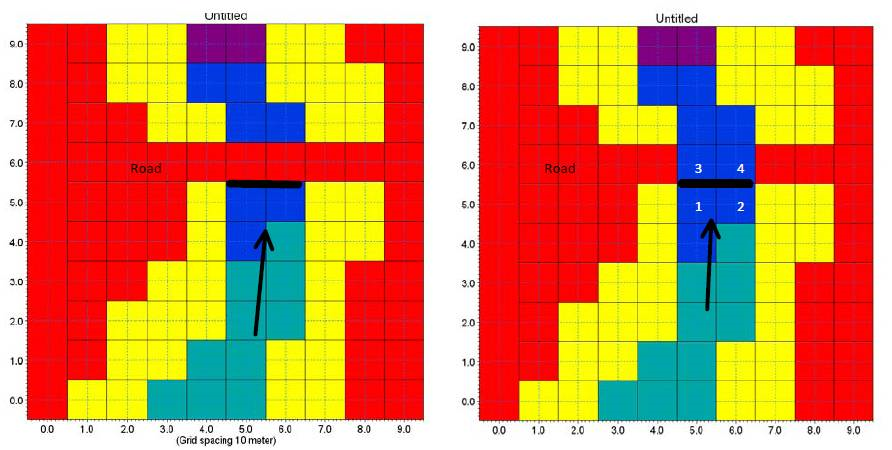
Figure: Setup of a short culvert
Note
If the overflow above the road needs to be represented, it can be computed using a weir placed at the same location as the short culvert.
Long Culvert
A long culvert is defined by a longitudinal line where inlet and outlet locations are defined with two end section lines at the ends of the longitudinal line, see figure below. The exact locations of the inlet and outlet in the numerical calculations are defined as a list of element faces, following the specified end section lines.
A long culvert is treated as two connected area sources (one at each end section). For each of the two end sections, the area is determined as the area of the elements to the right of the section of element faces. The total discharge through the culvert is calculated between these two areas using empirical formulas.
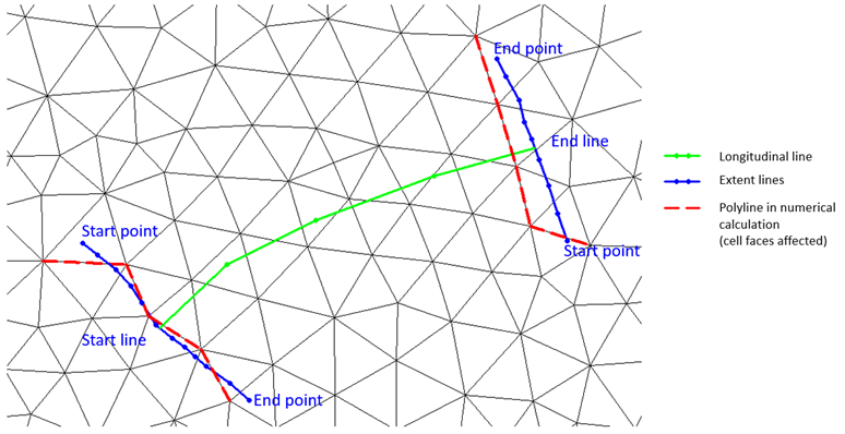
Figure: Definition sketch for a long culvert
Insert
From the MIKE+ interface, a short or long 2D culvert can be manually digitised in the 2D domain on the map.
Steps to digitize:
- Click on the "Insert" button at the top of the 2D culverts editor
- On the map, left click along the path of the culvert in the 2D domain. For a long culvert, the path to be digitized is the longitudinal line.
- Double click to complete the digitization.
- In the pop-up window, select whether the created culvert is a short or a long culvert. For a long culvert, specify the width of the two end section lines which will be automatically added at the ends of the digitized longitudinal line.
In the case of a long culvert, you can later click on the "Edit end sections coordinates" button to manually edit the locations of the extent lines if required (as shown in Long culvert figure).
Insert from File
The path of the culverts (i.e. the polylines shown on the map) can be imported from an external Shape file (.shp) file. This process creates new culverts for each polyline found in the source shape file (it e.g. does not update the location of existing culverts).
To import a shape file, click on 'Insert from file' button at the top of the 2D culverts editor. In the pop-up window, select whether to create short or long culverts.
When importing long culverts, it is possible to create culverts from their longitudinal and/or end section lines:
- If only the end section lines are imported: select the shape file containing polylines representing the end sections of the culverts. The shape file must contain two end section lines per culvert to create. While selecting the shape file:
- Define the map projection of the shape file
- Define the 'Matching key' field used to identify the culvert IDs and to associate the two end section lines together with a single culvert
- Tick or untick the culverts which should be imported or ignored.
- One culvert will be created for each selected ID, using the two end section lines imported from the shape file. The longitudinal line of the created culverts will be a straight line connecting the center of the two end section lines.
- If only the longitudinal lines are imported: select the shape file containing polylines representing the longitudinal lines of the culverts. While selecting the shape file:
- Define the map projection of the shape file
- Define the 'ID column name' field used to name the created culverts
- Tick or untick the culverts which should be imported or ignored.
- Then specify a width, which will control the width of the two end sections of the created culverts. These end section lines will be straight lines perpendicular to the imported longitudinal lines.
- If both types of lines are imported: one culvert will be created for each line from the longitudinal line shape file. The 'Matching key' field selected for the end sections shape file will be used to associate two end sections with each longitudinal line's ID,and must therefore match IDs from the 'ID column name' field from the longitudinal line shape file. The first end section is imported as upstream section, and the second as downstream section.
When importing short culverts, a single polyline shape file should be selected. While selecting the shape file:
- Define the map projection of the shape file
- Define the 'ID column name' field used to name the created culverts
- Tick or untick the culverts which should be imported or ignored.
The shapes of the imported can later be edited either on the map or in the 'Location' tab of the 2D culverts editor.
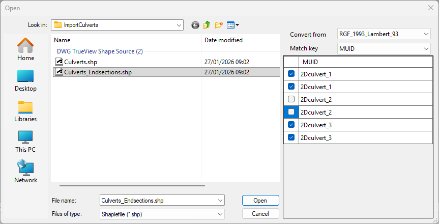
Figure: Selecting the culvert ID field and culverts to import from a shape file
Note
This 'Insert from file' function only imports the IDs and shapes / geometry of the 2D culverts, but cannot import other attributes of the culverts from fields in the shape file. If additional attributes shall be imported, use the 'Import and export' tool in 'Update' mode after creating the culverts with the 'Insert from file' function. Also note that the 'geometry' field of long culverts is a complex geometry combining the shapes of both end sections and longitudinal lines in a single field, and cannot be imported from the 'Import and export' tool. Therefore, to import both the shapes and other attributes for long culverts, it is mandatory to use successively the 'Insert from file' function and the 'Import and export' tool in 'Update' mode.
Location
The choice between a 'Short culvert' or 'Long culvert' type is visible and can be edited at the top of the tab.
For a short culvert, the coordinates of each point defining the polyline are shown in the 'Cross section' table, where they can be manually edited.
For a long culvert, the coordinates of each point defining the longitudinal polyline are shown in the 'Longitudinal location' table, where they can be manually edited. Additionally, the coordinates defining the two end section lines are available by clicking the 'Edit end sections coordinates' button.
In each of these tables, points can be added or removed from the polylines using the 'Insert' and 'Delete' buttons, or can be reordered using the 'Up' and 'Down' buttons.
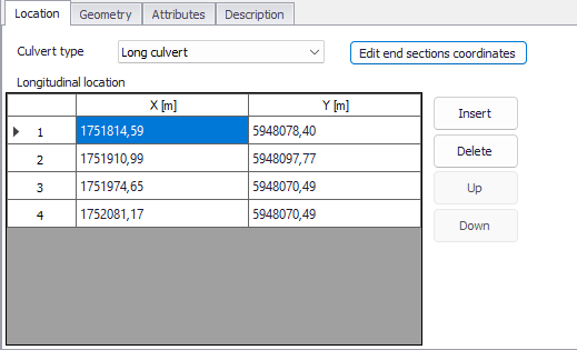
Figure: The Location tab in the 2D culverts editor
Geometry
The culvert geometry defines the geometrical shape of the active flow area of the culvert.
The location and geometrical layout of the culverts must be specified.
Figure: Setup definition of culvert
Geometry type
The cross-sectional geometry of a culvert can be specified as:
- Rectangular: The geometry is specified by the width and height.
- Circular: The geometry is specified by the diameter.
- Irregular Level-Width table: The geometry is specified using a level/width table. The Level/Width table defines the Culvert shape as a set of corresponding levels and flow widths. Values in the level column must be increasing.
Figure: Definition sketch for irregular culvert
No. of Culverts
'No. of Culverts' is a number identifying how many culverts exist at the specific culvert location with identical geometrical definition.
Example
Five identical shaped draining pipes are placed next to each other in an earth dam, and in order not to make 5 individual culvert definitions - one for each pipe - the 'No. of Culverts' in this case can be defined as 5 and the simulation engine will recognize that 5 culverts of identical shape and size are located here and flow calculations will take this into account accordingly.
Upstream Invert
Invert level to the left of the cross section for a short culvert and at the start line for a long culvert.
Downstream Invert
Invert level to the right of the cross section for a short culvert and at the end line for a long culvert.
Length
Length of the culvert.
Manning (M)
Manning's M bed resistance number along the culvert (for friction loss contribution). M = 1/n.
Attributes
Control which culverts are activated during the simulation using the "Apply" switch.
A number of parameters define the culvert characteristics as described in the following sections.
Dampening Delta Depth
When the water level gradient across a structure is small the corresponding gradient of the discharge with respect to the water levels is large. This in turn may result in a very rapid flow response to minor changes in the water level upstream and downstream. Alpha zero is the water level difference at which the discharge calculation is described by a linear variation. If the water level difference is below this value the discharge gradients are suppressed. The default setting is 0.01 meter. If a structure shows oscillatory behaviour it is recommended to increase this value slightly.
Non-Return Flap
The following options are available:
- None: No valve regulation applies (flow is not regulated).
- Only left to right flow: Only flow in the positive flow direction is allowed. Valve regulation does not allow flow in the negative flow direction in which case the flow through the structure will be zero. The flow direction is positive when the flow occurs from the right of the line structure to the left, positioned at the first point and looking forward along the line section.
- Only Negative Flow: Only flow in the negative flow direction is allowed. Valve regulation does not allow flow in the positive flow direction in which case the flow through the structure will be zero.
Figure: Positive and Negative flow direction definition for weirs and short culverts
Flow Distribution
For a short culvert the total discharge is calculated based on the mean water level in the real wet elements to the left and right of the section of faces. For a long culvert the total discharge calculated based on the mean water level in the real wet elements to the right of the section of faces for the two extent lines. The mean level is calculated using the length of the element faces as the weighting factor. Real wet elements are elements where the water depth is larger than the wetting depth. The upstream water level is then the highest of the two water levels and the downstream water level the smallest.
The distribution of the calculated total discharge along the section faces can be specified in two ways
- Uniform
- Non-uniform.
When the discharge for a short culvert is distributed to the 2D faces, if these elements are not wet, the discharge is distributed to the faces where the upstream elements are wet elements. When non-uniform distribution is applied the discharge will be distributed as it would have been in a uniform flow field with the Manning resistance law applied, i.e. relative to \(h^{5/3}\), where h is the total water depth.
When the discharge for a long culvert is distributed to the 2D faces, if no elements are wet, the discharge is distributed uniformly to all faces in the section. When non-uniform distribution is applied the same approach as for short culverts is used with the Manning resistance law applied. The non-uniform distribution is, in most cases, a good approximation. This does not apply if there are very large variations over the bathymetry or the geometry.
Note
For Composite structures the distribution for the first structure is applied.
Section Type
A culvert structure can be defined with either a Closed or an Open section type.
If set to open, the culvert will never run full or partially full, therefore only those flow conditions which represent a free water surface are modelled. When the water level is higher than the soffit the hydraulic parameters are calculated based on a section extended vertically upwards with a width equal to that at the soffit. For example, in the case of a rectangular section the height value is essentially redundant as the cross-section will be modelled as an open section of constant width.
In the case of a circular section, this switch is invalid and will be set to closed.
Momentum
For a long culvert it is possible to include or exclude a contribution to the momentum equations at the outlet location. This contribution is estimated as the discharge multiplied by a velocity. Here the magnitude of the velocity is calculated as the discharge divided by the local total water depth. The direction used for the two extent lines is the direction of the first and last segment of the transversal polyline. If the transversal polyline only contains one segment (two points), the direction is determined as the direction perpendicular to the line given by the first and last point of the extent line.
Head Loss Factors
The factors determining the energy loss occurring for flow through hydraulic structures.
The following head loss factors can be defined (for positive and negative flow directions):
- Inflow (contraction loss)
- Outflow (expansion loss).
For definition of flow direction for a short culvert refer to Non-Return Flap.
For a long culvert the flow direction is positive when flow is from the start line to the end line (see Long culverts).
Calibration factors
Calibration factors can also be applied besides head losses.
The total head loss, \(DH_{loss}\) through a culvert is given by:
(3.13) 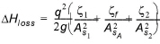
where \(A_{S1}\), \(A_{S2}\) and \(A_{S1}\) are the mean cross section areas along the length of the culvert and q is the discharge, \(z_{1}\) is the entrance or contraction loss coefficient, \(z_{2}\) is the outlet or expansion loss coefficient and \(z_{f}\) is the friction loss. \(z_{1}\) and \(z_{2}\) are calculated by
(3.14) 
(3.15) 
The upstream and downstream cross section areas, \(A_{1}\) and \(A_{2}\) are not processed and extracted in the present implementation and hence, defined as an infinite value. Contraction and expansion losses are therefore assumed to be applied in full using the defined inflow and outflow loss coefficients, \(z_{in}\) and \(z_{out}\). The friction loss coefficient is calculated using the Manning formula
(3.16) 
where L is the culvert length, n is Manning coefficient and R is the mean hydraulic radius along the culvert. The Manning's n-value depends on the interior surface of the culvert. Table values can be found in literature. For example, a concrete culvert n would typically range from 0.011 to 0.017.