CS/WD Network
MIKE+ offers tools targeted for editing Water Distribution or Collection System networks through the WD Network or CS Network menu (depending on the working model type).
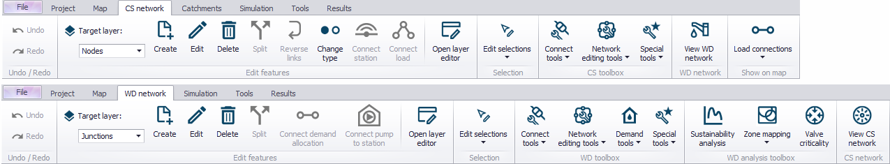
Undo/Redo

Offers Undo or Redo options during data editing.
Edit Features
The Edit Features Toolbox contains tools that are used for interactively laying out the model network on the Map. The list of tools within the toolbox are listed below.

Create
This tool is used graphically add a component by selecting the target layer and clicking within the Map view. Double click to end the feature creation.

Edit
For editing features i.e. moving nodes, realigning polyline features, or reshaping polygons. Right click outside the feature being edited to end the editing.

Delete
Deletes the selected features.

Split
This tool is used to graphically split links on the Map.

Reverse links
This tool is used to swap the pipe orientation (i.e. From and To Nodes) for a selected pipe on the Map.

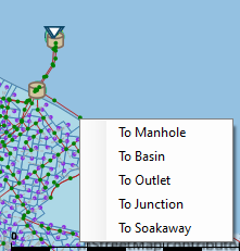
Change type
Option for CS Nodes. Option to quickly change the Node Type of a selected node on the Map (e.g. from Manhole to Outlet).

Open layer editor
Offers quick access to the Editor of the model feature selected from the Map. The editor is opened as a new tab document on the main window.
Selection
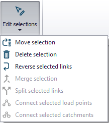
The 'Edit selections' list contains tools for editing/manipulating selected elements:
- Move selection
- Delete selection
- Reverse selected links: swap the From and To Nodes for links
- Merge selection: for merging selected elements.
- Split selected links: opens a dialog offering options for dividing the link geometry into more segments. This tool only applies to pipes (not to structure links).
- Connect selected demand allocations (WD)
- Connect selected pumps to pump station (WD)
- Connect selected load points (CS)
- Connect selected catchments (CS)
CS/WD Toolbox
This toolbox in MIKE+ includes specific tools for Water Distribution or Collection System models, which are used to connect, edit and simplify models. The available tools depend on the active model type.
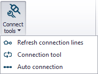
Click on WD/CS network tab, then in the ‘WD/CS toolbox’, you will find Connect tools, Network editing tools and Special tools.
Connect Tools (WD)
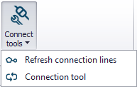
Refresh connection lines
Apply this tool to refresh or recreate the connection lines (e.g. to measurement stations), in case they do not appear properly on the map.
Connection tool
Use the tool to configure automatic (bulk) connection of model features (demand allocations or measurement stations) to the WD network.
Also see chapter Connection Tool for related information.
Connect Tools (CS)
Refresh connection lines
Apply this tool to refresh or recreate the connection lines (e.g. to measurement stations or catchments), in case they do not appear properly on the map.

Connection tool
Use the tool to configure automatic (bulk) connection of model features (e.g. catchments, load points, measurement stations) to the CS network.
Also see chapter Connection Tool for related information.

Auto connection
Tool for making connections between 1D networks. Use the tool to configure the automatic (bulk) creation of connections between network layers, e.g. an overland flow network and underground sewer network (i.e. 1D/1D models).
Chapter Auto Connection Tool has more details on the Auto Connection tool.
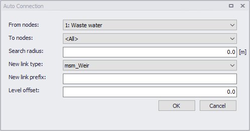
Figure: Auto connection tool dialog
Network Editing Tools
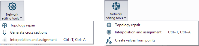
MIKE+ network editing tools provide automatic re-interpretation of features and attributes, when the imported model data does not compare to reality. The tools offered by MIKE+ allows a batch repair of the network at once, rather than a case by case scenario, by either using topology repair or by interpolating and assigning records accordingly.

Topology repair
Offers a way to detect and repair topology or network geometry issues in the model.
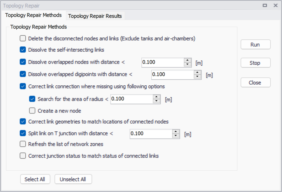
Figure: Topology repair in MIKE+
The following methods can be applied to the repair process:
- Delete disconnected nodes and links: isolated nodes (other than tanks) and links / pipes, disconnected from the rest of the network, will be removed.
- Dissolve self-intersecting links: when a link is self-intersecting (drawing a loop on the map, and crossing its own polyline), this operation will remove a vertex from the polyline. If the link is still self-intersecting after the operation, this operation must be repeated as necessary to remove more vertices. This operation also removes links which use the same node as 'From node' and as 'To node'.
- Dissolve overlapped nodes: when the distance between two nodes is smaller than the specified search radius, one of the nodes will be removed. Connected links are reconnected accordingly afterwards.
- Dissolve overlapped digipoints: when the distance between two digipoints (intermediate points defining the link's polyline) is smaller than the specified search radius, some digipoints will be removed.
- Correct link connection where missing: when a link's end is not connected to a node, this operation will connect it either to the closest existing node within the specified search radius, or to a new node. If the two options (search for existing nodes and create new ones) are enabled, the operation will first search for existing nodes, and will create a new one only if no existing node is found in the search radius.
- Correct link geometries to match locations of connected nodes: when a link's end appears disconnected on the map from the node it is actually connected to in the editors, this operation will update the shape of the link on the map so that the end of the link is moved to the node's location. This visual disconnection can e.g. occur when working with scenarios, after applying some combinations of changes to link geometry and node locations.
- Split link on T-junction: when the end of a link overlaps a second link, this second link is split at the intersection and a node is inserted, and all the three resulting pipes are connected to this new node.
- Refresh the list of network zones: for Water Distribution projects, this operation refreshes the list of network zones in the 'Zones' editor, based on the information from the 'Zone ID' fields in the various network editors (pipes, junctions, etc.).
- Correct junction status to match status of connected links: for Water Distribution projects, the 'Is active' option should normally be automatically unticked when all connected links are set to inactive, and ticked otherwise. This operations forces to update the status for this 'Is active' option for junctions, based on the status of connected links. This update may e.g. be required in some specific cases where data and statuses are imported using the 'Import and export' tool.
After running the tool, the 'Topology Repair Results' tab will list all the issues found, and the changes that have been applied. For items edited or inserted, double-clicking in the first column of this table will zoom to the corresponding item on the map.

Generate cross sections (For CS models)
Use the tool to derive CRS cross section data from terrain data. See Chapter Cross Section Generation tool for details.

Interpolation and assignment
This tool allows you to derive (missing) model parameter values from other model or data layer information. More details on the tool are found in chapter Interpolation and Assignment Tool.
Create valves from points (For WD models)
This tool allows you to insert new valves in the network. It will split pipes when necessary, and insert the new valves at locations defined by points in a selected shape file. The main valves' properties can be read from the attributes of the shape file. More details on the tool are found in chapter Create Valves from Points Tool.
Special Tools
MIKE+ offers special tools for model simplification and feature editing. This includes the following:

Network simplification
This tool offers options for simplifying the model network through:
- Trimming: Removal of network inside an area of interest.
- Merging: Simplification of network by removal of interior nodes.
Chapter Simplification Tool gives more details on Network Simplification in MIKE+.

Submodel manager
The Submodel Manager tool is used to create models where a specified area of interest is detailed, and the remainder of the model is simplified. See chapter Submodel Manager for more details.

Spatial processing
This tool offers spatial processing tools for model features, such as clipping, erasing, merging, etc.
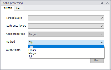
Figure: Spatial processing in MIKE+

Lateral snapping (For CS models)
The Lateral Snapping tool is used for automatically move nodes and snapping them laterally to the lowest DEM value along a lateral snap alignment.
See Chapter Lateral Snapping Tool for more details on the tool.
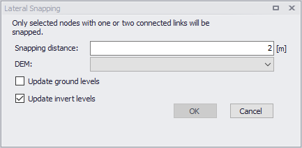
Figure: Lateral Snapping tool

Duplicate pipe parameters (For WD models)
Allows you to select pipes from the Map and duplicate their attributes to pipes with missing attributes, such as diameter, material, etc. The tool automatically duplicates the selected parameter to all pipes that are adjacent to the selected pipe(s) until a "T" or other complex junction exists.
Aggregation (For WD models)
The Aggregation tool allows to develop total junction demands based on demand connections.

Distributed demand (For WD models)
The Distributed demands tool allows you to distribute a portion of a total demand (to be specified by the user) to every pipe in the network.
![]()
Set pumps critical levels (For CS models)
The tool 'Set pumps critical levels' assigns a critical level at pumping stations' wet well nodes, computed from the geometry of the network upstream of the pumps.
See Chapter 52 Set Pumps Critical Levels Tool (p. 959) for more details on the tool.
WD Analysis Toolbox
Several special analysis tools are offered by MIKE+ for Water Distribution models.

Sustainability analysis
The tool helps understand WD simulation results and analyze them for possible problems, anomalies, critical areas, and similar.

Zone mapping
Zone Mapping offers two different ways to generate "zones" in the model, which can then be displayed on the map:
- Create zones from network separators: this first option creates zones based on the network topology and geometry, closed pipes, closed valves, and pumps.
- Create zones from GIS layer: this second option assign zones to the network elements using a layer of polygons providing the extent of the various zones.
Defining zones helps to visualise how different network parts are hydraulically interconnected and where the HGL line breaks. It helps understand the hydraulic behaviour of the network prior to running the hydraulic simulation, and also helps detect possible errors in the network connectivity.

Valve criticality
The Valve Criticality tool allows analysis of a valve from the valve layer to determine which valves need to be closed in order to replace the selected valve.
CS/WD Network

This functionality allows you to overlay and view another model type (e.g. CS) on top of the active model (e.g. WD). Note, this tools only allows you to view the other network model. To edit the other model network, change the Model Type under the Project menu.
Show on map
This group contains two tools to check connections of load points to the collection system network on the map.
![]()
This tool highlights all the load points connected to the currently active network.
Remove graphical highlights using the 'Clear highlighted' tool in the 'Map' tab.
![]()
This tool highlights all the load points without connections to the currently active network.
Remove graphical highlights using the 'Clear highlighted' tool in the 'Map' tab.