LID Properties Editor
The MIKE+ LID Properties editor organizes the data input for the different layers and functional elements of LID structures. The input data is organized into the following group and tabs:
- Identification: This group holds information on unique LID IDs. Each LID is generic and is specified per unit area. As such, it can be replicated and placed in any sub-catchment of the study area (i.e. deployed) with different actual sizes and in any number of instances.
- General: Tab where LID type is defined.
- LID components tabs (Surface, Soil, Pavement, Storage, Drain, Drainage Mat, Roof Drain, and Pollutants Removal tabs): The properties of layers and functional elements constituting a LID type are entered in these tab pages.
Notes
Only the relevant data fields and tabs for a LID type are activated and available for data input.
Some components/functionalities are optional for some LID types.
Identification
The identification group box displays element ID information. Use the Insert or Delete buttons to add or remove records from the editor, respectively.
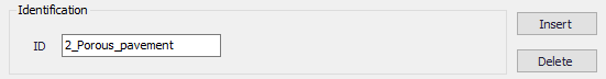
Figure: LID Properties Identification group
General
Define LID type on the General tab page of the LID Properties editor.
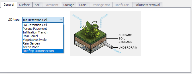
Figure: The General tab of the LID Properties editor
| Edit field | Description | Used or required by simulations | Field name in data structure |
|---|---|---|---|
| ID | ID of the LID element | Yes | MUID |
| LID Type | Type of LID 1: Bio Retention Cell 2: Porous Pavement 3: Infiltration Trench 4: Rain Barrel 5: Vegetative Swale 6: Rain Garden 7: Green Roof 8: Rooftop Disconnection | Yes | LIDTypeNo |
Table: Edit fields in the LID Properties Identification group and General tab (mss_LIDControl)
Surface
A Surface component is used for the following LID structures:
- Bioretention Cell (LIDTypeNo = 1)
- Porous Pavement (LIDTypeNo = 2)
- Infiltration Trench (LIDTypeNo = 3)
- Vegetative Swale (LIDTypeNo = 5)
- Rain Garden (LIDTypeNo = 6)
- Green Roof (LIDTypeNo = 7)
- Rooftop Disconnection (LIDTypeNo = 8).

Figure: The LID Properties editor Surface tab
| Edit field | Description | Used or required by simulations | Field name in datastructure |
|---|---|---|---|
| Storage Depth | When confining walls or berms are present this is the maximum depth to which water can pond above the surface of the unit before overflow occurs (in inches or mm). For LIDs that experience overland flow it is the height of any surface depression storage. For swales, it is the height of its trapezoidal cross section. | Yes If LIDTypeNo <> 4 | StorHt |
| Vegetative Volume | The fraction of the storage area above the surface that is filled with vegetation | Yes If LIDTypeNo <> 4 or 8 | VegFrac |
| Surface Roughness | Manning's n for overland flow over the surface of porous pavement or a vegetative swale. See Table 4.29 . Use 0 for other types of LIDs. | Yes If LIDTypeNo <> 4 | Rough |
| Surface Slope | Slope of porous pavement surface or vegetative swale (percent). Use 0 for other types of LIDs | Yes If LIDTypeNo <> 4 | Slope |
| Swale Side Slope | Slope (run over rise) of the side walls of a vegetative swale's cross section. This value is ignored for other types of LIDs | Yes If LIDTypeNo = 5 | Xslope |
Table: Edit fields in the LID Properties Surface tab (mss_LIDControl)
Soil
A Soil component is used for the following LID structures:
- Bioretention Cell (LIDTypeNo = 1)
- Rain Garden (LIDTypeNo = 6)
- Green Roof (LIDTypeNo = 7)
- Porous Pavement (LIDTypeNo = 2) (optional).
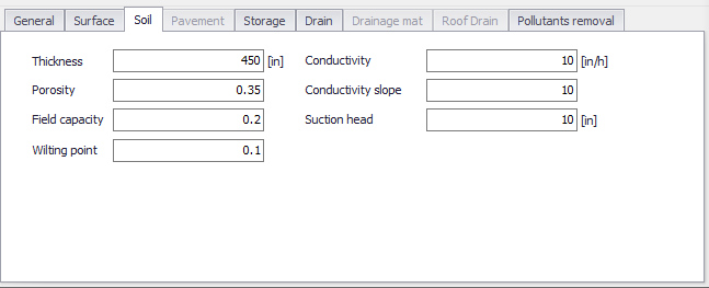
Figure: The LID Properties editor Soil tab
| Edit field | Description | Used or required by simulations | Field name in datastructure |
|---|---|---|---|
| Thickness | The thickness of the soil layer (inches or mm). Typical values range from 18 to 36 inches (450 to 900 mm) for rain gardens, street planters and other types of land-based bio-retention units, but only 3 to 6 inches (75 to 150 mm) for green roofs. Set Thickness = 0 when unused. | Yes If LIDTypeNo = 1, 6, 7, 2 | SThick |
| Porosity | The volume of pore space relative to total volume of soil (as a fraction). | Yes If LIDTypeNo = 1, 6, 7, 2 | Por |
| Field Capacity | Volume of pore water relative to total volume after the soil has been allowed to drain fully (as a fraction). Below this level, vertical drainage of water through the soil layer does not occur. | Yes If LIDTypeNo = 1, 6, 7, 2 | FC |
| Wilting Point | Volume of pore water relative to total volume for a well dried soil where only bound water remains (as a fraction). The moisture content of the soil cannot fall below this limit. | Yes If LIDTypeNo = 1, 6, 7, 2 | WP |
| Conductivity | Hydraulic conductivity for the fully saturated soil. This is equivalent to leakage capacity | Yes If LIDTypeNo = 1, 6, 7, 2 | Ksat |
| Conductivity Slope | Slope of the curve of log (conductivity) versus soil moisture content (dimensionless). Typical values range from 5 for sands to 15 for silty clay | Yes If LIDTypeNo = 1, 6, 7, 2 | Kcoeff |
| Suction Head | The average value of soil capillary suction along the wetting front. This is the same parameter as used in the Green-Ampt infiltration model | Yes If LIDTypeNo = 1, 6, 7, 2 | Suct |
Table: Edit fields in the LID Properties Soil tab (mss_LIDControl)
Note
Set Soil Thickness to 0 if it is unused for a LID.
Pavement
A pavement component is used for Porous Pavements (LIDTypeNo = 2).
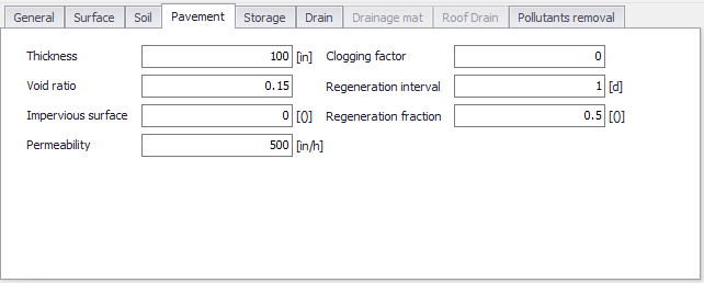
Figure: The LID Properties editor Pavement tab
| Edit field | Description | Used or required by simulations | Field name in datastructure |
|---|---|---|---|
| Thickness | The thickness of the pavement layer (inches or mm). Typical values are 4 to 6 inches (100 to 150 mm) | Yes If LIDTypeNo = 2 | PThick |
| Void Ratio | The ratio (expressed as a fraction) of the volume of the pores or interstices of a material to the total volume of the pavement. Typical values range from 0.11 to 0.17 for pavements Note that porosity = void ratio/(1 + void ratio). | Yes If LIDTypeNo =2 | PVratio |
| Impervious Surface | Ratio of impervious paver material to total area for modular systems; 0 for continuous porous pavement systems | Yes If LIDTypeNo = 2 | FracImp |
| Permeability | Permeability of concrete or asphalt used in continuous systems or hydraulic conductivity of the fill material (gravel or sand) used in modular systems. Permeability of new porous concrete or asphalt is high (>2450 mm/h), but over time the fine particles in the runoff tend to clog the pavement, reducing the permeability of the structure. | Yes If LIDTypeNo = 2 | Perm |
| Clogging Factor | Number of pavement layer void volumes of runoff treated it takes to completely clog the pavement. Use a value of 0 to ignore clogging. Clogging progressively reduces the pavement's permeability in direct proportion to the cumulative volume of runoff treated. Max. value = 1. | Yes If LIDTypeNo = 2 | PVclog |
| Regeneration Interval | The number of days that the pavement layer is allowed to clog before its permeability is restored. A value of 0 indicates that no permeability regeneration occurs. | Yes | PRegInterval |
| Regeneration Fraction | The fractional degree to which the pavement's permeability is restored when a regeneration interval is reached. A value of 0 means no restoration while a value of 1 indicates complete restoration to the original permeability value. Once a regeneration occurs the pavement begins to clog once again at a rate determined by the Clogging Factor. | Yes | PRegFraction |
Table: Edit fields in the LID Properties Pavement tab (mss_LIDControl)
Storage
A Storage component is used for the following LID structures:
- Bioretention Cell (LIDTypeNo = 1)
- Porous Pavement (LIDTypeNo = 2)
- Infiltration Trench (LIDTypeNo = 3)
- Rain Barrel (LIDTypeNo = 4).
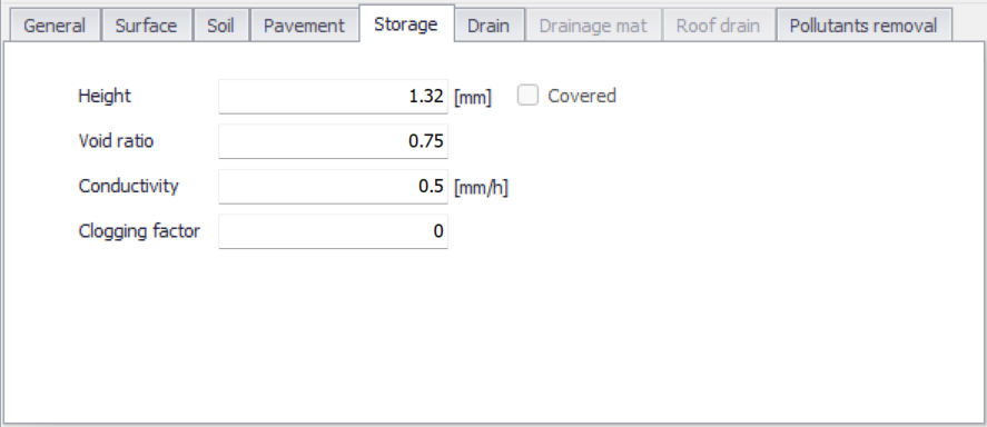
Figure: The LID Properties editor Storage tab
| Edit field | Description | Used or required by simulations | Field name in datastructure |
|---|---|---|---|
| Height | This is the height of a rain barrel or thickness of a gravel layer (inches or mm). Crushed stone and gravel layers are typically 6 to 18 inches (150 to 450 mm) thick while single family home rain barrels range in height from 24 to 36 inches (600 to 900 mm). | Yes If LIDTypeNo = 1,2,3,4 | Height |
| Void Ratio | The volume of void space relative to the volume of solids in the layer. Typical values range from 0.5 to 0.75 for gravel beds. Note that porosity = void ratio / (1 + void ratio). | Yes If LIDTypeNo = 1,2,3 | SVratio |
| Conductivity | The maximum rate at which water can flow out the bottom of the layer after it is first constructed (in/hr or mm/hr). | Yes If LIDTypeNo = 1, 2, 3 | Filt |
| Clogging Factor | Total volume of treated runoff it takes to completely clog the bottom of the layer divided by the void volume of the layer | Yes If LIDTypeNo = 1,2,3 | SVclog |
| Covered | Determines whether the rain barrel is covered or not. A non-covered rain barrel receives rainfall, but a covered one does not. | Yes If LIDTypeNo = 4 | LidCoveredNo |
Table: Edit fields in the LID Properties Storage tab (mss_LIDControl)
Drain
A Drain component is used for the following LID structures:
- Bioretention Cell (LIDTypeNo = 1) (optional)
- Porous Pavement (LIDTypeNo = 2) (optional)
- Infiltration Trench (LIDTypeNo = 3) (optional)
- Rain Barrel (LIDTypeNo = 4).
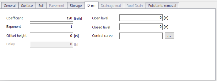
Figure: The LID Properties editor Drain tab
| Edit field | Description | Used or required by simulations | Field name in datastructure |
|---|---|---|---|
| Coefficient | Coefficient C that determines the rate of flow through the underdrain as a function of height of stored water above the drain height. If the layer has no drain then set C to 0. | Yes If LIDTypeNo = 1,2,3,4 | Coeff |
| Exponent | Exponent n that determines the rate of flow through the underdrain as a function of height of stored water above the drain height. A typical value for n is 0.5 (making the drain act like an orifice). | Yes If LIDTypeNo = 1,2,3,4 | Expon |
| Offset Height | Height of any underdrain piping above the bottom of a storage layer or rain barrel (inches or mm). | Yes If LIDTypeNo = 1,2,3,4 | HOffset |
| Delay | The number of dry weather hours that must elapse before the drain line in a rain barrel is opened (the line is assumed to be closed once rainfall begins). | Yes If LIDTypeNo = 4 | Delay |
| Open Level | The height in the drain´s storage Layer that causes the drain to automatically open when the water level rises above it. Default is 0 which indicates disabled | No | OpenLev |
| Closed Level | The height in the drain´s storage level that causes the drain to automatically close when the water level falls below it. Default is 0 | No | ClosedLev |
| Control Curve | The name of an optional control curve that adjust the computed drain flow as function of the head of water above the drain. Leave blank if not applicable | No | ControlCurveID |
Table: Edit fields in the LID Properties Drain tab (mss_LIDControl)
The drain coefficient C and exponent n determines the rate of flow through a drain as a function of the height of stored water above the drain's offset.
Note
Set the coefficient to 0 when a drain is not used.
The following equation is used to compute this flow rate per unit area of the LID unit:
(4.1) \(q = Ch^{n}\)
where \(q\) is outflow (in/hr or mm/hr) and \(h\) is the height of saturated media above the drain (inches or mm).
Note
The units of \(C\) depend on the unit system being used as well as the value assigned to \(n\).
Drainage Mat
A Drainage Mat component is used for Green Roofs (LIDTypeNo = 7).
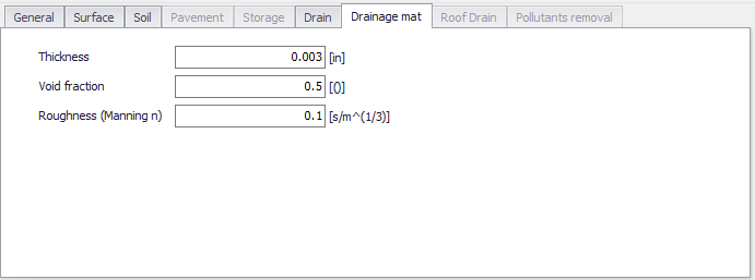
Figure: The LID Properties editor Drainage Mat tab
| Edit field | Description | Used or required by simulations | Field name in datastructure |
|---|---|---|---|
| Thickness | The thickness of the mat or plate. It typically ranges between 25 to 50 mm | Yes If LIDTypeNo = 7 | DMThick |
| Void Fraction | The ratio of void volume to total volume in the mat. It typically ranges from 0.5 to 0.6 | Yes If LIDTypeNo = 7 | DMVFractiony |
| Roughness | Manning´s n used to compute the horizontal flow rate of drained water through the mat. In absence of standard product specifications provided by manufacturers, the roughness must be estimated. One may use n values from 0.1 to 0.4 (M = 2.5 - 10). | Yes If LIDTypeNo = 7 | DMRough |
Table: Edit fields in the LID Properties Drainage Mat tab page (mss_LIDControl)
Roof Drain
Define Rooftop Disconnection (LIDTypeNo = 8) flow capacity on the Roof Drain tab page of the editor.
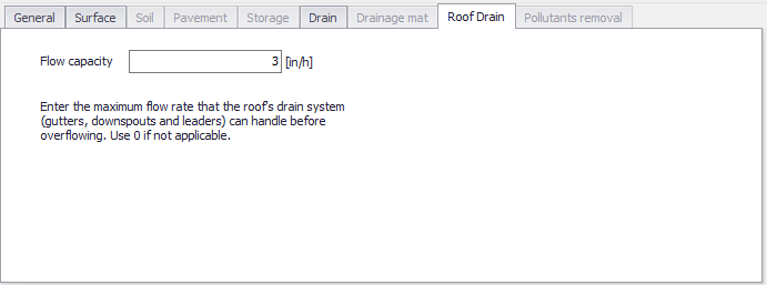
Figure: The LID Properties Roof Drain tab
| Edit field | Description | Used or required by simulations | Field name in datastructure |
|---|---|---|---|
| Flow Capacity | Maximum flowrate the roof gutters and downspouts can handle (in inches/hour or mm/hour) before overflowing. | Yes If LIDTypeNo = 8 | RDFlowCap |
Table: Edit fields in the Roof Drain tab (mss_LIDControl)
Pollutants Removal
The Pollutants Removal page of the LID Properties editor allows one to specify the degree to which pollutants are removed by a LID unit as seen by the flow leaving through its underdrain system. Hence, it only applies to LIDs with underdrain:
- Bioretention Cell (LIDTypeNo = 1)
- Porous Pavement (LIDTypeNo = 2)
- Infiltration Trench (LIDTypeNo = 3)
- Rain Barrel (LIDTypeNo = 4).
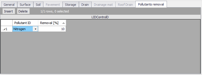
Figure: The Pollutants Removal tab
| Edit field | Description | Used or required by simulations | Field name in datastructure |
|---|---|---|---|
| Pollutant ID | Pollutant treated by the LID (see Pollutants editor) | Yes If LIDTypeNo = 1,2,3,4 | PollutantID |
| Removal [%] | Percent of pollutant removed by the LID | Yes If LIDTypeNo = 1,2,3,4 | Removal |
Table: Edit fields in the Pollutants Removal tab page secondary table (mss_LIDControl)
The page has a secondary table where entries are made for pollutant ID and the percent removal treated by the LID unit. The default status is blank interpreted as percent removal being 0.
The removals specified are applied to the LIDs underdrain when it sends flow onto either a subcatchment or into a conveyance system node. They do not apply to any surface flow that leaves the LID unit.
As an example (taken from EPA SWMM 5.1 Help manual), if the runoff treated by the LID unit had a TSS concentration of 100 mg/L and a removal percentage of 90, then if 5 cfs flowed from its drain into a conveyance system node, the mass loading contribution to the node would be 100 x (100 - 90) x 5 x (28.3 \, \(\text{L}/\text{ft}^{3}\)) = 1,415 mg/sec.
If in addition the unit had a surface outflow of 1 cfs into the same node, the mass loading from this flow stream would be 100 x 1 x 28.3 = 2,830 mg/sec.
Example Manning Coefficient and Soil Characteristics Values
The table below shows examples of Manning M and n values for different types of surfaces.
| Surface Type | Manning M | n |
|---|---|---|
| Smooth asphalt | 91 | 0.011 |
| Smooth concrete | 83 | 0.012 |
| Ordinary concrete lining | 77 | 0.013 |
| Good wood | 71 | 0.014 |
| Brick with cement mortar | 71 | 0.014 |
| Vitrified clay | 67 | 0.015 |
| Cast Iron | 67 | 0.015 |
| Corrugated metal pipes | 42 | 0.024 |
| Cement rubble surface | 42 | 0.024 |
| Fallow soils (no residue) | 20 | 0.05 |
| Cultivated soils | ||
| Residue cover \< 20% | 17 | 0.06 |
| Residue cover \> 20% | 6 | 0.17 |
| Range (natural) | 8 | 0.13 |
| Grass | ||
| Short, prairie | 7 | 0.15 |
| Dense | 4 | 0.24 |
| Bermuda grass | 2 | 0.41 |
| Woods | ||
| Light underbrush | 2.5 | 0.4 |
| Dense underbrush | 1.25 | 0.8 |
| Source: McCuen, R. et al. (1996), Hydrology, FHWA-SA-96-067, Federal Highway Administration, Washington, DC. |
Table: Example surface Manning M and n values for porous pavement or vegetative swale
The two tables below show example hydraulic conductivity properties for various porous media.
| Material | Hydraulic Conductivity, K (cm/s) | Porosity, h (%) |
|---|---|---|
| Gravel | 10 -1 - 10 2 | 25 - 40 |
| Sand | 10 -5 - 1 | 25 - 40 |
| Silt | 10 -7 – 10 -3 | 35 - 50 |
| Clay | 10 -9 – 10 -5 | 40 - 70 |
| Source: Freeze, R.A., and Cherry, J.A., (1979), Groundwater, Prentice-Hall, Englewood Cliffs, NJ. |
Table: Example hydraulic conductivity and porosity values for unconsolidated porous media
| Soil Texture Class | Hydraulic Conductivity, K (in/hr) | Suction Head, Ψ (in.) | Porosity, ϕ (fraction) | Field Capacity, FC (fraction) | Wilting Point, WP (fraction) |
|---|---|---|---|---|---|
| Sand | 4.74 | 1.93 | 0.437 | 0.062 | 0.024 |
| Loamy Sand | 1.18 | 2.40 | 0.437 | 0.105 | 0.047 |
| Sandy Loam | 0.43 | 4.33 | 0.453 | 0.190 | 0.085 |
| Loam | 0.13 | 3.50 | 0.463 | 0.232 | 0.116 |
| Silt Loam | 0.26 | 6.69 | 0.501 | 0.284 | 0.135 |
| Sandy Clay Loam | 0.06 | 8.66 | 0.398 | 0.244 | 0.136 |
| Clay Loam | 0.04 | 8.27 | 0.464 | 0.310 | 0.187 |
| Silty Clay Loam | 0.04 | 10.63 | 0.471 | 0.342 | 0.210 |
| Sandy Clay | 0.02 | 9.45 | 0.430 | 0.321 | 0.221 |
| Silty Clay | 0.02 | 11.42 | 0.479 | 0.371 | 0.251 |
| Clay | 0.01 | 12.60 | 0.475 | 0.378 | 0.265 |
| Source: Rawls, W.J. et al., (1983). J. Hyd. Engr., 109:1316. |
Table: Example soil characteristics values