Outlet Head Loss
MIKE+ models outlet head losses at nodes. The general flow equations are valid only for continuous conduits, where the only resistance to flow is bottom and sidewall friction. Hydraulic conditions in nodes, i.e. at manholes and structures, serve as boundary conditions in the computation of flows in conduits. In turn, hydraulic conditions in a node depend on the flows in the inlet and outlet conduits.
These hydraulic conditions, expressed in terms of the energy conservation principle, are calculated as water levels and velocity heads. The calculation is based on the mass continuity and formulation of more or less advanced energy relation between the node and the neighbouring links, including energy losses caused by local flow disturbances at different locations in the node.
The following parameters constitute a definition of head loss calculation option in MIKE+:
Computation Method
Three different methods are available:
- Classic: This is a simplified computational model for energy losses in junctions based on F.A. Engelund's energy loss formulae. The total head loss comprises of node inlet loss and node outlet loss, including losses due to change in flow direction, due to change in elevation, and due to contraction, if relevant.
- Mean Energy Approach: This is an alternative solution which fully ignores the energy loss at the inlet. For a flow-through manhole, this means that the energy level in the manhole is set equal as at the downstream end of the inlet pipe. For manholes with multiple inlets, the energy level is calculated as the weighted average of the inlet flows (i.e. large flows contribute most to the energy level). In this formulation, the total loss at the manhole is concentrated computationally at the outlet, and can be fully controlled by the user.
- No Head Losses: This option ignores all local losses. Regardless of the shape of the outlets, geometrical set-up of the junction and distribution of flows among inlet and outlet conduits, water levels in the junction and the outlet conduit are set equal as if there is no change of geometry and flow conditions between the junction and outlet conduit. This means that this option should be applied only where there is no change in cross section. Inconsistent results may be generated if inappropriately applied. This option is recommended for an artificial node/junction along a straight section of conduit, where no losses actually occur.
Further details on the various head loss computation methods mentioned above are found in the MIKE 1D Reference Manual.
Effective Node Area
This parameter is only relevant for the Classic head loss computational method. In all other cases, the default total wetted node area is applied. The following choices are available:
- Full Node Area: Calculated as product of diameter and water depth for manholes and read from the basin geometry table (Ac) for basins. Typically results in overestimate of local loss in a node.
- Calculated Effective Area: The effective area in a manhole is calculated based on an empirical formula (see Section 4.6.2 ‘Headloss calculation for inflowing water’ section in the MIKE 1D Reference Manual). This results in a significantly smaller area than full wetted area and, consequently, with a more realistic flow calculation.
- Reduced Calculated Effective Area: The effective area in a manhole is further reduced to 50% of the calculated effective area.
Loss Coefficient
The available loss coefficient types distinguish three different interpretations of the specified head loss coefficient.
- Km: Interprets the specified value as the outlet 'shape' coefficient Km (see Equation (4.17) in MIKE 1D Reference Manual).
- Contraction HLC: Interprets the specified value as the outlet 'contraction' coefficient zcontr(j) (see Equation (4.17) in MIKE 1D Reference Manual). This means that the model ignores the geometrical relations between the node and the outlet links (outlet shape), and applies the specified value directly as the zcontr. The contraction losses in the outlet links are then computed by multiplying the velocity head in the respective link by the zcontr. The total head loss for an outlet link is computed as a sum of the contraction, direction and elevation loss.
- Total HLC: Interprets the specified value as the total outlet head loss. This means that the model completely ignores the geometry of the node/links, and applies the specified value (Total HLC) directly as the zout, the same for all outlet links at the node. The total head losses in the outlet links are then computed by multiplying the velocity head in the respective link by the specified zout.
Changes to outlet head loss parameter sets used for Nodes are made via the 'Outlet head loss' editor. The figure below also lists five pre-defined head loss parameter sets in MIKE+.
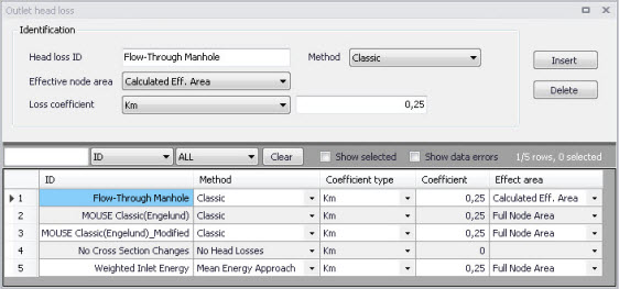
Figure: Outlet Head Loss editor
| Edit field | Description | Used or required by simulations | Field name in datastructure |
|---|---|---|---|
| Head Loss ID | Unique head loss parameter set identifier | Yes | MUID |
| Method | Dropdown menu to select head loss calculation method for parameter set: - Classic - No Head Losses - Mean Energy Approach | Yes | OutletShapeNo |
| Effective Node Area | Choice of method for the calculation of wetted area: - Full Node Area - Calculated Eff. Area - Reduced Calculated Eff. Area | Yes If Method = Classic | EffAreaNo |
| Loss Coefficient [dropdown menu] | Definition of the interpretation of the head loss coefficient: -Km - Contraction HLC - Total HLC | Yes If Method = Classic or Mean Energy Approach | CoeffNo |
| [Field next to Loss Coefficient dropdown menu] | Value for the loss coefficient | Yes If Method = Classic or Mean Energy Approach | Coeff |
Table: Outlet head loss parameter set editor attributes (Table msm_LossPar)