Simulation Setup
MIKE+ simulations are started from the 'Simulation specifications' section. Individual simulations can be configured and run from the 'Simulation setup' editor, each e.g. using different modules, simulation periods or time setp settings.
Once configured, individual simulations can be executed in batch mode from the Batch simulation editor, applying an automatic and sequential launch of several simulation setups.
Info
Simulations can also be executed without opening the editor, through command lines. Refer to Section Predefined export from command lines for more information.
There are six primary tabs in the Simulation setup editor:
- General
- Simulation Period
- HD parameters
- WQ parameters
- Water Hammer
- Output.
The table at the bottom of the editor contains an 'Active simulation' check box, which flags a simulation setup as the one in use by default, for instance when starting the simulation using the Ctrl+R shortcut or using a command line. Only one simulation at a time may be set as "Active".
This table also includes a 'Pattern ID' column, which use is optional. It is a default pattern which is applied to all demands without any pattern.
Figure: Layout of the Simulation setup editor
Main buttons
The following buttons are also located at the top of the editor with the Identification group:
- Insert: Inserts a new record in the Simulation Setup editor
- Copy: Duplicates an existing (currently active) simulation setup record
- Delete: Deletes a currently active simulation record
- RUN: Triggers export of the current simulation job and execution of the simulation.
Identification
The 'Identification' group at the top contains the ID field. This is the user-specified ID of simulation. This ID will be reflected in the name of result files.
General
A description of all options available in the General tab follows.
Figure: The General tab
Simulation definition
The 'Simulation definition' group box offers the following settings:
- Scenario ID: select the scenario which is to be executed in the active simulation ID
- Description: the description field is an optional field with further details about the simulation.
Basic modules
There are five types of modules in this field:
- Steady state simulation: EPANET-based steady state analysis
- Extended Period Hydraulics: EPANET-based extended period simulation
- Extended Period Water Quality: Chemical concentration (compute chemical concentration), Water Age (compute water age), Source Tracing (trace flow from a specific node)
- Multi-species water quality: EPANET MSX-based analysis of multiple, interacting chemical species
- Water hammer.
Water quality modules are normally disabled but users can enable them by opening ‘Model type’ under General settings and activating the appropriate modules.
When a water quality module is selected, two simulation modes are available: you can either run both hydraulics and water quality simulations at the same time, or you can run only the water quality simulation using an "hydraulics" file resulting from an earlier hydraulics simulation. The latter helps reducing simulation times when the hydraulic simulation takes a long time and does not need to be repeated while running the water quality scenarios. The input hydraulics file is saved from the hydraulics simulation by selecting 'Save hydraulics file' in the 'Output' tab.
Simulation Period
This section controls the simulation duration. It has two ways:
- Define the simulation start time and simulation end time
- Define the duration directly.
A text field box to define the starting time of the simulation and the other to establish the end time of it. It can be defined that the start and end of the simulation directly from the text box by typing the date or by means of using the pop up calendar window (accessible through the arrow on the right corner of the box).
The default start time is current date and time on the computer while the end time is 1 day after the default start time.
Alternatively, once the initial date of the simulation has been set the user can define the duration of simulation in the duration section using the day, hour, minutes and second fields.
A Gantt graphic calendar visualization of the simulation period is presented on the right as additional aid to comprehend the extension and make corrections if needed.
'Reset time period' button allows to clear all settings and reset the time and duration to default values.
Figure: Layout of Simulation Period tab
HD parameters
Figure: Layout of HD parameters tab
The following parameters are available in the 'HD parameters' tab:
- Time Step: This section defines the time step of each simulation run, such as hydraulic time step, pattern time step and quality time step.
- Hydraulic time step: The time step (sometimes called the time interval), which is used to model the simulation in steps, that is how often a new hydraulic computation of the pipe network system is to be computed. This is typically 5 minutes by default.
- Pattern time step: This data entry is optional, and specifies the length of time between each pattern change (e.g., the period of time over which water demands and constituent source strengths remain constant). If necessary, MIKE+ will adjust the specified Hydraulic Time Step so that it is not greater than the specified Pattern Time Step. The default value is 5 minutes.
- Quality time step: This data entry is used for water quality analysis, and specifies the time step to be used to track water quality changes in the pipe network system. If this entry is left blank, the program then uses an internally computed time step based upon the smallest time of travel through any pipe in the network. The default value is 5 minutes.
- Properties: These data entries allow you to determine the hydraulic and water quality behaviour of the pipe network should be analysed.
- Specific Gravity: This data entry specifies the specific gravity of the fluid at the temperature condition being simulated. This data entry allows fluids other than water to be simulated. Gravity is the weight per unit volume of the fluid being modelled relative to water. Specific gravity is the ratio of the density of the fluid being modelled to that of water at 4 deg. C. (unitless).
- Viscosity: This data entry specifies the kinematic viscosity of the fluid at the temperature condition being simulated. The units of viscosity are ft2/sec (or m2/sec for SI units). The viscosity is the kinematic viscosity of the fluid being modelled relative to that of water at 20 deg. C (1.0 centistoke). The default value is 1.0.
- Molecular Diffusivity: This data entry specifies the molecular diffusivity of the chemical being tracked. The diffusivity is the molecular diffusivity of the chemical being analysed relative to that of chlorine in water. The default value is 1.0. Diffusivity is only used when mass transfer limitations are considered in pipe wall reactions. A value of 0 will cause MIKE+ to ignore mass transfer limitations.
- Emitter Exponent: Power to which pressure is raised when computing the flow through an emitter device. The textbook value for nozzles and sprinklers is 0.5. This may not apply to pipe leakage.
- Convergence: This section allow you to determine how the hydraulic and water quality behaviour of the pipe network should be analysed.
- Maximum numbers of trials
- Accuracy: Convergence criterion used to signal that a solution has been found to the nonlinear equations that govern network hydraulics. Trials end when the sum of all flow changes divided by the sum of all link flows is less than this number. Suggested value is 0.001.
- Max Head Error: Convergence criterion requiring that the head loss computed by the head loss formula compared to the difference in nodal heads across each link be less than the specified value. When the value is 0 or empty, the criterion is ignored. This criterion is only available when using the EPANET 2.2 version.
- Max. Flow Change: Convergence criterion requiring that the largest absolute flow change between the current and previous solutions be less than the specified value. When the value is 0 or empty, the criterion is ignored. This criterion is only available when using the EPANET 2.2 version.
- Water Quality Tolerance: Smallest change in quality that will cause a new parcel of water to be created in a pipe. A typical setting might be 0.01 for chemicals measured in mg/L as well as water age and source tracing. The Quality Tolerance determines when the quality of one parcel of water is essentially the same as another parcel. For chemical analysis this might be the detection limit of the procedure used to measure the chemical, adjusted by a suitable factor of safety. Using too large a value for this tolerance might affect simulation accuracy. Using too small a value will affect computational efficiency.
- Maximum Number of Segments: Maximum number of segments, which could be generated for a pipe during the water quality analysis. The default is left as blank.
- Unbalanced System: Action to take if a hydraulic solution is not found within the maximum number of trials. Choices are STOP to stop the simulation at this point or CONTINUE to use extra trials, with no link status changes allowed, in an attempt to achieve convergence. For the CONTINUE option, the number of extra trials must be specified.
- CheckFreq: This sets the number of solution trials that pass during hydraulic balancing before the status of pumps, check valves, flow control valves and pipes connected to tanks are once again updated. The default value is 2, meaning that status checks are made every other trial. A value equal to the maximum number of trials would mean that status checks are made only after a system has converged. (Whenever a status change occurs the trials must continue since the current solution may not be balanced.) The frequency of status checks on pressure reducing and pressure sustaining valves (PRVs and PSVs) is determined by the DampLimit option (see below).
- MaxCheck: MAXCHECK is the number of solution trials after which periodic status checks on pumps, check valves flow control valves and pipes connected to tanks are discontinued. Instead, a status check is made only after convergence is achieved. The default value is 10, meaning that after 10 trials, instead of checking status every CheckFreq trials, status is checked only at convergence.
- DampLimit: This is the accuracy value at which solution damping and status checks on PRVs and PSVs should begin. Damping limits all flow changes to 60% of what they would otherwise be as future trials unfold. The default is 0 which indicates that no damping should be used and that status checks on control valves are made at every iteration. Damping might be needed on networks that have trouble converging, in which case a limit of 0.01 is suggested.
WQ parameters
The WQ parameters tab allows to specify the rate at which a constituent decays (or grows) by reaction as the constituent travels through the pipe network. It can be enabled only when the water quality module is ticked in ‘Model type’ editor.
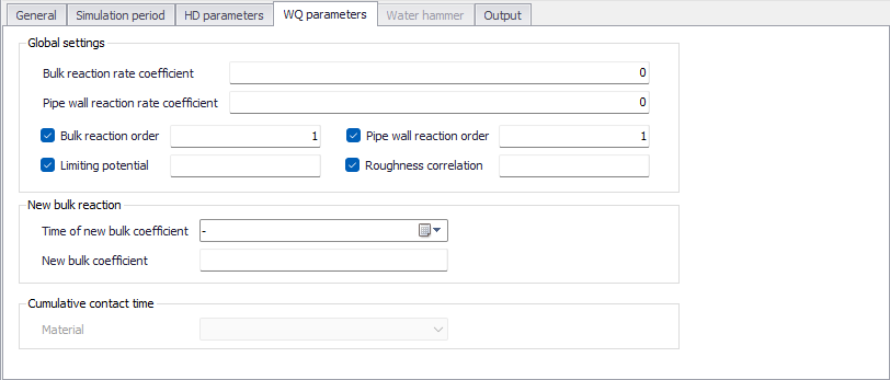
Figure: Layout of WQ parameters tab
The following parameters are available in the 'WQ parameters' tab:
- Bulk Reaction Rate Coefficient: This data entry defines the bulk reaction rate that is applied to all flow in the pipe network system. Units for bulk reaction rates are in days–1. Note that this reaction rate coefficient is applied globally to the entire pipe network.
- Pipe Wall Reaction Rate Coefficient: This data entry defines the pipe wall reaction rate that is applied to all flow in the pipe network system. Units for pipe wall reaction rates are in ft/day (or m/day). Note that this reaction rate coefficient is applied globally to the entire pipe network. One method that can be used to compare the relative magnitude of the pipe wall reaction rate with the bulk reaction rate is to divide the pipe wall reaction rate coefficient by the hydraulic radius of the pipe (i.e., 1/2 the pipe radius). The resulting quantity will have the same units as the bulk reaction rate coefficient, days–1.
- Bulk Reaction Order: Power to which concentration is raised when computing a bulk flow reaction rate. Use 1 for first-order reactions, 2 for second-order reactions, etc. Use any negative number for Michaelis-Menton kinetics. If no global or pipe-specific bulk reaction coefficients are assigned then this option is ignored.
- Pipe Wall Reaction Order: Power to which concentration is raised when computing a bulk flow reaction rate. Choices are 1 for first-order reactions or 0 for constant rate reactions. If no global or pipe-specific wall reaction coefficients are assigned then this option is ignored.
- Limiting Potential: This setting specifies that reaction rates are proportional to the difference between the current concentration and some limiting potential value. This value can be locally overwritten by limiting potential values specified in water quality settings of the 'Pipes' editor.
- Roughness Correlation: This setting will make all default pipe wall reaction coefficients be related to pipe roughness in the following manner.
- New Bulk Reaction: At a certain time level, the bulk coefficient will change to a new value. This section defines the new value of bulk coefficient and the time the new bulk coefficient would start. After the start time, the simulation would apply the new bulk coefficient for calculation.
Output
In this section, users can select from the following to store simulation results:
- Use default folder and file name: save outputs in the folder containing the MIKE+ project
- Use this folder: save outputs in a custom folder but with a default file name
- Use this folder and file name: save outputs in a custom folder and with a custom file name
Report time step: time interval between times at which computed results are reported. Normal default is 1 hour.
Report start time: time that the report starts. For example, if the report start time is 5 hours, the report would start 5 hours later from the simulation start time.
Statistics: Type of statistical processing used to summarize the results of an extended period simulation. Choices are:
- Without Statistics (results reported at each reporting time step)
- Average (time-averaged results reported)
- Minimum (minimum valve results reported)
- Maximum (maximum valve results reported)
- Range (difference between maximum and minimum)
Report raw results: when this option is selected, the hydraulic results will be reported "as computed" regardless of the physical meaning of the values. In some cases, this may result in showing very large negative pressures "infinitely high" and flows in pipes where it is not possible to supply water due to negative pressures.
Save hydraulics file: when this option is selected, a hydraulics file is saved from the hydraulics simulation, for later use as input for a decoupled water quality simulation. This option is only available for 'Steady state simulation' and for 'Extended period hydraulics'.
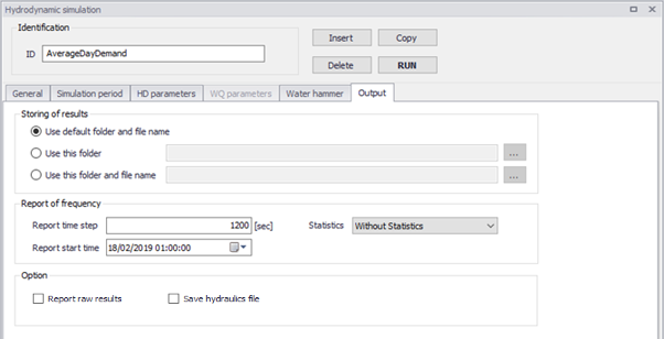
Figure: Layout of Output tab
A predefined list of result items is saved in the result files during the simulation. This list is supplemented by a number of "derived items", which are computed in memory when the result files are loaded in MIKE+. The following table lists these two types of result items.
| Items saved in result files | Derived items |
|---|---|
| Node water demand (outflow, inflow) Node head (hydraulic grade line) Node pressure Node water quality (water age, source trace, chemical) Tank water demand (outflow, inflow) Tank head (water level elevation) Tank pressure (water depth) Tank water quality (water age, source trace, chemical) Link (pipe) flow Link (pipe) velocity (absolute) Link (pipe) headloss per 1000 Link (pipe) water quality Link (pipe) status code (open, closed, check valve) Link (pipe) setting (friction) Link (pipe) reaction rate Link (pipe) friction factor Valve flow Valve velocity Valve headloss per 1000 Valve water quality Valve status code (closed, open, active) Valve setting Valve reaction rate Valve friction factor Pump flow Pump velocity Pump headloss per 1000 Pump water quality Pump status code (closed, open) Pump setting (relative speed) Pump reaction rate Pump friction factor |
Link (pipe) flow (absolute): absolute value of the flow in the pipe Link (pipe) pressure gradient: Difference in pressure grade line between beginning and end nodes of the pipe Valve flow (absolute): absolute value of the flow in the valve Valve pressure gradient: Difference in pressure grade line between beginning and end nodes of the valve Pump flow (absolute): absolute value of the flow in the pump Pump pressure gradient: Difference in pressure grade line between beginning and end nodes of the pump Link Accumulated flow: Volume accumulated over time, computed from the link flow time series. The accumulated value increases when the flow is positive and decreases when the flow is negative Link Accumulated Flow (Absolute): Volume accumulated over time, computed from the absolute link flow time series. The accumulated value always increases, even when the flow changes direction. |
Table: Summary of result items available in result files and as derived items
Refer to the 'Results Presentation' chapter in the Model Manager guide for mode details about loading results in MIKE+.