Cross Section Tree
The Cross Section tree window on the Cross Sections editor shows a list of all cross sections available in the setup.
In the first column, cross sections are identified by their river name, Topo ID, and chainage.
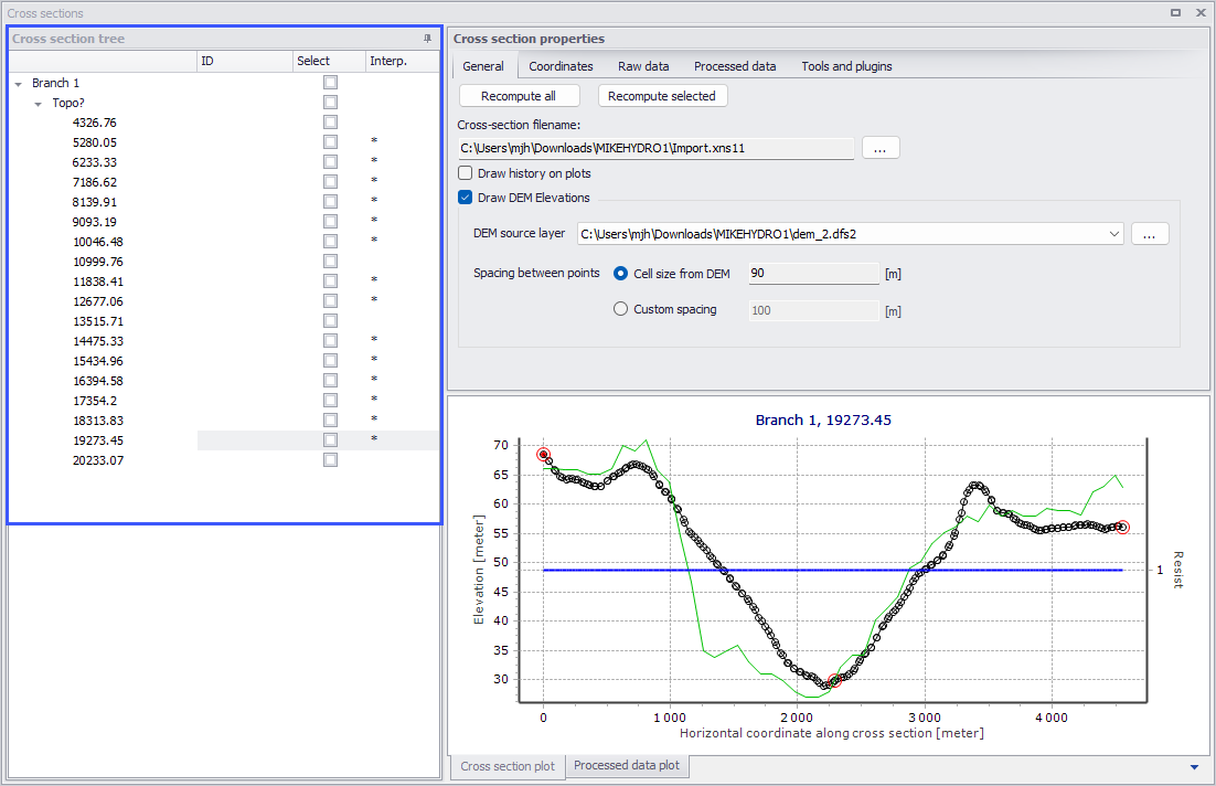
Figure: The Cross Section Tree window on the left side of the Cross Sections editor
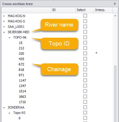
Figure: Cross Section Tree data columns
Clicking on a cross section in the tree view will show properties for this cross-section on the right-hand side of the editor.
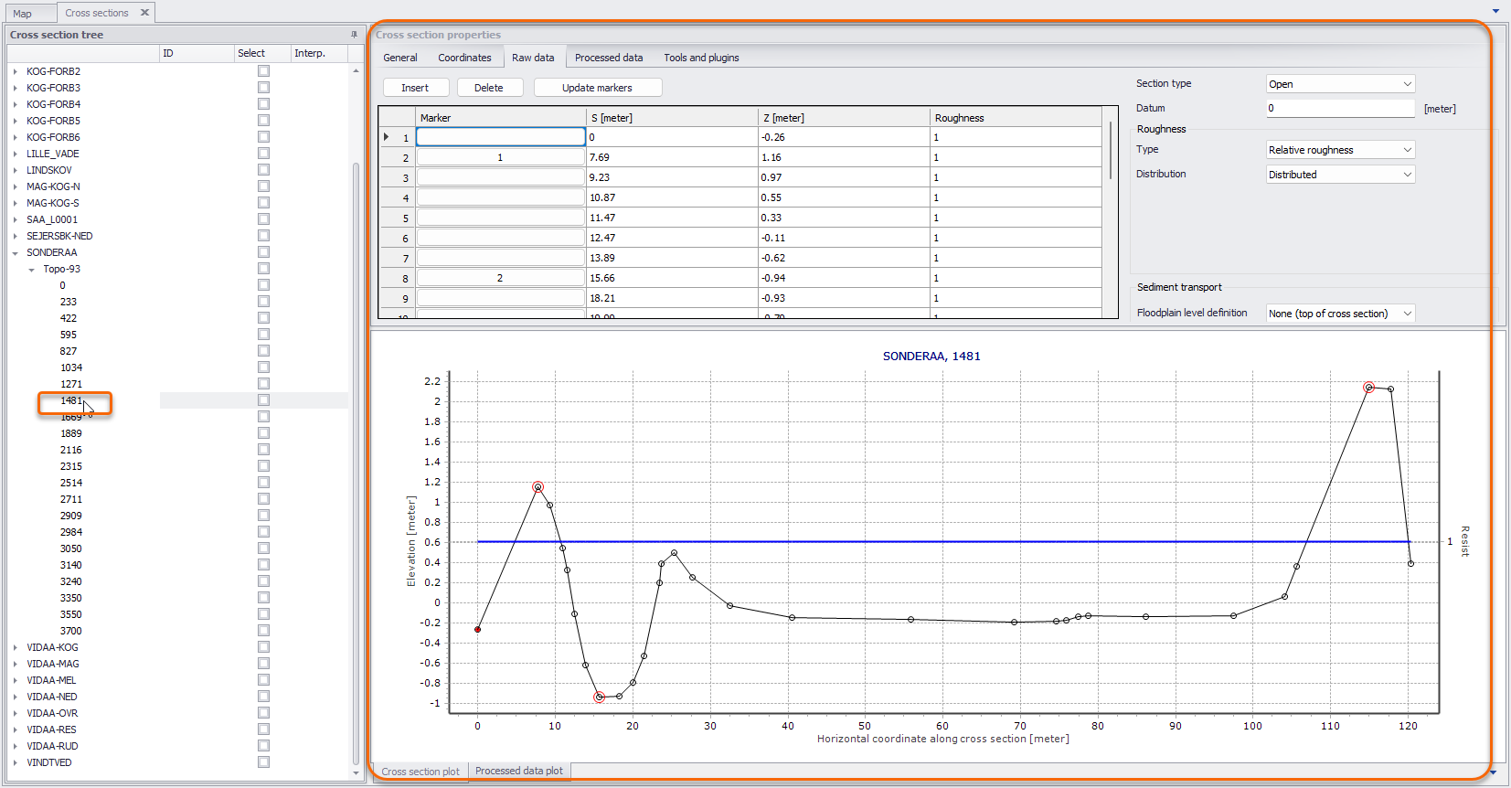
Figure: Cross Section Properties on the right side of the editor
Right-clicking in the first column gives access to options to edit the cross sections. The context menu options slightly vary according to where you clicked on the tree view. For instance, clicking on a single chainage allows editing the corresponding cross section only, whereas clicking on the Topo ID or on the river name allows editing all or a selection of cross sections.
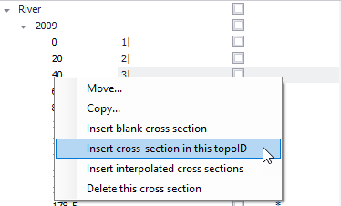
Figure: Context menu options when right-clicking on a cross section chainage
The ‘Move…’ option allows moving cross sections to different locations, by changing either the river name, Topo ID and/or chainage. When selecting the ‘Move…’ option, the dialog in the figure below appears, where the ‘From’ groupbox indicates which cross sections are being moved and the ‘To’ groupbox indicates the destination which has to be specified by the user.
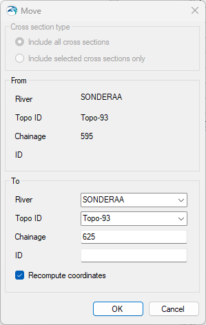
Figure: The Move dialog for relocating a cross section
The ‘From’ groupbox shows the original chainage only when moving a single cross section. It shows the Topo ID only when moving a single cross section or a group of sections from a given Topo ID.
If the option 'Recompute coordinates' is selected, the coordinates of the cross section will be updated, assuming that the cross section is a straight line perpendicular to the river, crossing the river at the location of the Marker 2. If the option is not selected, the coordinates will remain identical to the original coordinates, and therefore the cross section will remain at the same location on the map despite the change of chainage. In case of inconsistency between the chainage location and the coordinates, the actual location used in the simulation will be the chainage value.
Note
The upper part of the dialog (‘Cross section type’) is only active when selecting ‘Move…’ from a river name or a Topo ID (figure above). It allows selecting between moving all the cross sections of the river/Topo ID, or only the selection. These options are therefore not relevant for moving a single cross section.
The ‘Copy…’ option is similar to the ‘Move…’ except that the original cross sections are kept at their original locations.
To insert a cross section, it is possible to use the ‘Insert blank cross section’ option, which allows creating a cross section on any river and for any Topo ID, specified as shown in the figure below.
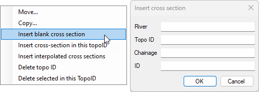
Figure: ‘Insert blank cross section’ option dialog
Alternatively, the ‘Insert Cross Section in this Topo ID’ option allows inserting a cross section under the corresponding Topo ID. The Topo ID (and river name) are automatically filled, as illustrated in the figure below.
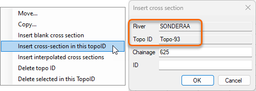
Figure: ‘Insert cross section in this topo ID’ option dialog
The ‘Insert Cross Section in this River’ option is available from the context menu when right-clicking on the river name. It allows for inserting a cross section under the selected river name. The river name is automatically filled, and the Topo ID and Chainage need to be specified.

Figure: ‘Insert cross section in this river’ option dialog
It is possible to insert additional cross sections interpolated from initially available (e.g. surveyed) data using the 'Insert interpolated cross sections' option from the context menu on the Cross Section Tree.
This opens the Insert Interpolated Cross Sections dialog shown in the figure below, where the river name and Topo ID where interpolation shall be conducted must be selected. It is possible to interpolate a single cross section at a given chainage or multiple cross sections. In the latter case, a maximum distance between the interpolated cross sections must be specified, along with the range of chainages where interpolation is conducted.
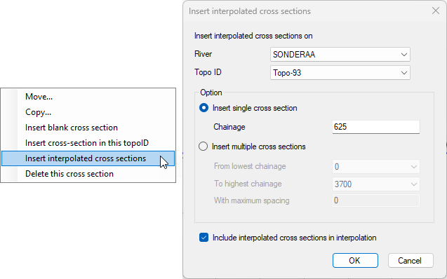
Figure: ‘Insert interpolated cross sections’ option dialog
Info
Tools for automatic creation of cross sections (from e.g. survey points and/or DEM) or automatic import from text files are also available in the ribbon, in the 'River network' tab.
There are also multiple options for deleting cross sections. Right-clicking on a single cross section gives access to the ‘Delete this cross section’ feature. Clicking on the Topo ID allows deleting either all cross sections under this Topo ID (using the ‘Delete topo ID’ option) or only the selected sections under the Topo ID (using the ‘Delete selected in this topo ID’ option). Finally, clicking on the river name allows deleting either all cross sections under the river (using the ‘Delete river’ option) or only the selected sections under the river name (using the ‘Delete selected in this river’ option).
The Cross Section Tree panel also has the following columns:
- ID: The second column contains user defined identifiers. To add or edit an ID, click on the field for the relevant cross section.
- Select: The third column contains a checkbox that allow selecting and deselecting cross sections. Selections may later be used to process multiple cross sections at the same time, for instance to edit their properties.
- Interp: The last column contains a symbol for cross sections created by interpolation from other cross sections. This allows keeping track of the origin of cross section data.
Note
Per default, cross sections are sorted by increasing chainage under each river and Topo ID. It is however possible to sort them by decreasing chainage by clicking in the header of the first column, or sort them by their attributes (ID, selected/unselected, interpolated) by clicking on the appropriate column header.