Turbines
A turbine is a type of rotating equipment designed to remove energy from a fluid. For a given flow rate, turbines remove a specific amount of the fluid’s energy head. Each turbine is mechanically coupled with a generator that converts rotational energy to electrical energy. Each generator’s output terminal transmits electricity to the distribution grid.
Turbines are either defined interactively on the graphical Map window using the Add Turbine tool (see figure below), or by manual data entry using the Turbine editor.
The Turbine editor allows you to define the turbine ID, location, properties, energy generated, regulation and description.

Figure: The Turbine editing tools
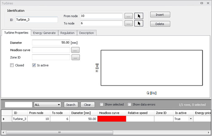
Figure: The Turbine editor allows to define the storage tank node that supply water to the water distribution network
A list of the Turbine editor attributes follows, with a short description given for each one.
Identification
Turbine ID (mandatory)
This data entry is used to specify an ID which uniquely identifies the turbine link. The turbine ID acts as a unique lookup key that identifies the link from all other links. A link can be a pipe, turbine, valve or turbine. Therefore, no two links may have the same ID. The check would be instant, when the user types an ID already used, there will be a hint beside the field and the user would not be able to type anything else (see Figure 1.4).
However, a link and a node (i.e., junction, reservoir, or tank) can have the same ID. The link ID value can be any string value (up to 40 characters).
A new turbine ID is automatically suggested by MIKE+ whenever a new turbine is placed into the list by pressing «Insert». When defining the turbine graphically on the Map window using the Add Turbine tool, the turbine ID is automatically defined.
FROM NODE, TO NODE (mandatory)
These data entries define the ID of the turbine’s starting (upstream) and ending (downstream) nodes. These IDs define the turbine connectivity of the network.
Clicking  , the ID selector window pops up and the pull-down selection list allows to specify what type of node is connected to the pump. The type selection is either Junction or Tank. Then the user can choose the appropriate node on the list below. Clicking
  , it allows the user to graphically select the node from the Map window and the connection of pipe will be changed simultaneously on the map.
Turbine flow is always assumed to move from the starting (upstream) node to the ending (downstream) node.
Turbine properties
This tab gives basic information of turbines.
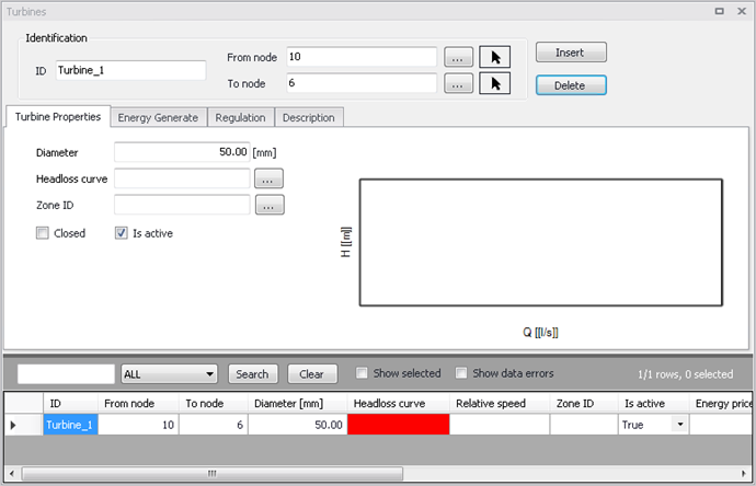
Figure: The general turbine information
Diameter
This data entry allows you to define the Turbine size.
Headloss Curve
A Headloss Curve is used to describe the headloss (Y in feet or meters) through a turbine as a function of flow rate (X in flow units). Clicking  , headloss curve list pops up and it allows users to specify the headloss curve. The headloss curve would be plotted on the right after it defines.
Zone ID
This is an optional name for the zone to which the turbine belongs. When a zone ID is specified, this zone will be listed in the 'Zones' editor. The '…' button can be used to select an existing zone.
Is active
It defines whether the turbine is active or not. If the turbine is active, it will be included in the simulations, otherwise it will be omitted.
Energy Generate
This tab defines the parameters for calculating how much energy or money each turbine can generate from the generator.
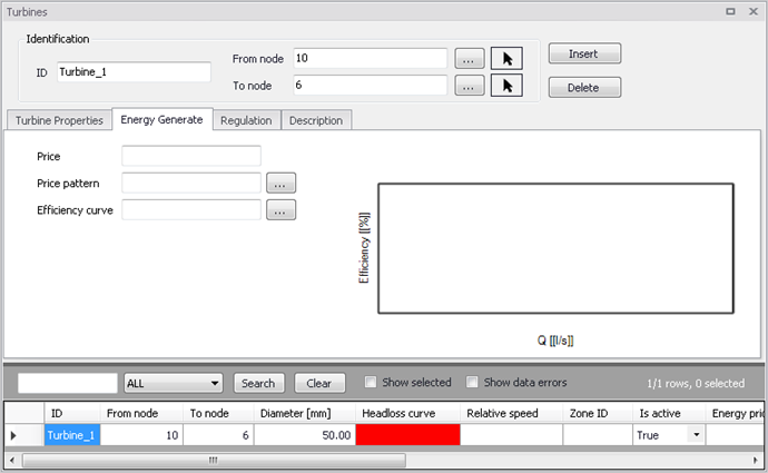
Figure: The 'Energy generate' tab
Price
The user defines an energy price ($/kw-hour) to be used. In this method, MIKE+ determines the energy generated by the turbine in kw-hours and multiplies the energy production by the price.
Leave blank if not applicable or if the global value supplied with the Parameters in Cost Analysis will be used.
Price Pattern
It allows engineers to specify a multi-step tariff to describe the variation in energy price throughout the day. The multi-step tariff is stored as a pattern, each multiplier in the pattern is applied to the pump's Energy Price to determine a time-of-day pricing for the corresponding period.
Leave blank if not applicable or if the global pricing pattern specified in the project's Energy Options will be used.
Efficiency Curve
It allows engineers to specify a curve that used for turbine efficiency (\(\eta\)) as a function of flow rate (\(Q\)). This curve is used to calculate the electrical energy that turbine can extract from the water flows. The function is stated below:
\(P = \eta \rho Q g h\)
Where:
- \(P\) is power in watts
- \(\eta\) is the dimensionless efficiency of the turbine
- \(\rho\) is the density of the water in kilograms per cubic metre
- \(Q\) is the flow in cubic metres per second
- \(g\) is the acceleration due to gravity in meters per square second
- \(h\) is the height difference between inlet and outlet in meters
The curve is created in curves and relations table (see Curve and Relations section), and can then be selected in the 'Turbines' editor using the '...' button.
Regulation
This tab defines the regulation of turbine to control their operation. Turbines may change their state as storage tanks fill and empty, or pressure change throughout the network system. There are only two states of a turbine: open or close.
For each turbine, it can create a control table to add or delete the regulation statements. The regulations would be shown in a graph next to the table.
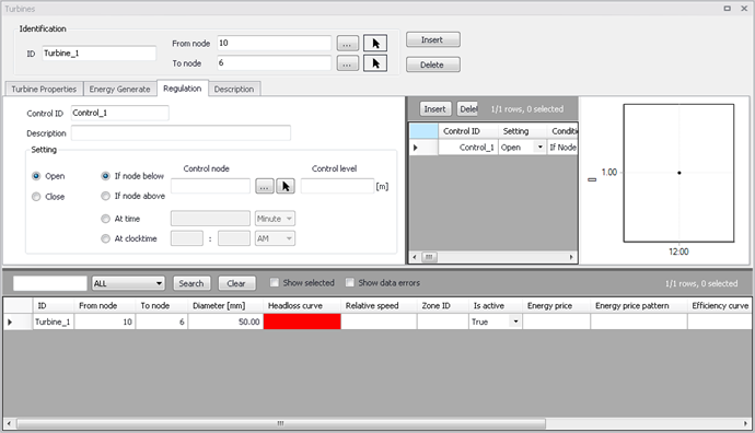
Figure: The Regulation of turbines
A list of the data entries for Regulations follows.
Control ID
The ID of the control.
Description
An optional description of the control.
Setting
The settings contain three parts:
- Action
- Condition type
- Condition.
A radio button is used to set an Action. A turbine can only be set to Open or Close.
A radio button is used to set the Condition type, i.e. the type of condition that will trigger the action:
- If node below/above: This rule will execute the action if the pressure level in a specified node is above or below a specified level.
- At time: This rule will execute the action when the specified amount of time since simulation start has passed. When setting up a series of these rules there will be a time series of the setting in the right window.
- At clocktime: This rule will execute the action every day at the specified time.
The available Condition settings will depend on the selected condition type:
- When "If node below/above" is selected, the user must specify a node or tank ID in the first field and the threshold pressure level in the second field. Note that this is defined as the pressure at Elevation level for a node, and the pressure at Base elevation for a tank.
- When "At time" is selected, the user must specify a number and a time unit (hours/minutes) since start of simulation.
- When "At clocktime" is selected the user must specify a time of day in hours, minutes and AM/PM.
Description
This data entry allows to enter a description identifying the turbines being entered. This description can be optionally displayed on the Map window and in reports generated by the Report Generator.
Data Source (optional)
This data entry is used to specify a corresponding asset data source, which uniquely identifies the turbine location (such as database table or a database file name) in the asset management system.
Asset ID (optional)
This data entry is used to specify a corresponding asset turbine ID, which uniquely identifies the turbine in the asset management system (such as GIS, for example).
Status (optional)
This drop down selection list data entry allows you to define whether the turbine is imported (i.e existing link was imported from the external data source), or is inserted, modified, GIS, calibrated or similar. By default, turbine status is undefined.
Add Picture
The 'Add picture' button allows to add photo for individual item. Once loaded from external source, the picture will be displayed on the right side.
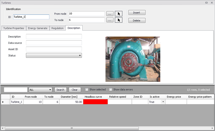
Figure: The Description of turbines