Nodes
This editor allows defining node elements such as manholes, basins, soakaways or outlets.
The editor organizes the related input data into the following groups:
- Identification: ID and location of the node
- Geometry: nodes’s type and shape
- Cover: cover type for manhole
- Flow regulation: maximum inflow; in/exfiltration;
- Head loss: information on the head loss approach and coefficients
- Pressure node: used for tail nodes of pressurized branches.
- Soakaway: infiltration parameters
- Description: descriptive fields.
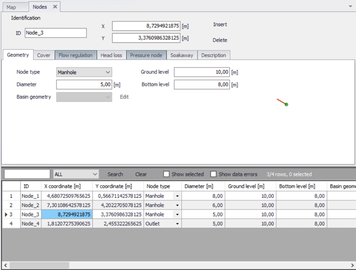
Figure: Nodes and Structures editor
The buttons 'Insert' and 'Delete' allow addition and deletion of nodes in the editor.
Identification
General properties for nodes are specified under the Identification group:
- ID: Unique identifier for the node.
- X and Y coordinates: The X and Y coordinates are used to define the physical (map) location of the node. When defining the node graphically on the Map using the drawing tools, the X and Y coordinates are automatically filled.
- Apply: This check box allows to toggle the active status of the node on and off. The simulations will omit all nodes that are not active.
| Edit field | Description | Used or required by simulations | Field name in data structure |
|---|---|---|---|
| NodeID | A unique name for the node. Up to 40 characters (letters, numbers, blank spaces and underscore characters). Identical names with different case are not allowed | Yes | MUID |
| X coordinate | X coordinate of the node position | Yes | GeomX |
| Y coordinate | Y coordinate of the node position | Yes | GeomY |
| Apply | This check box allows to toggle the active status of the node on and off. The simulations will omit all nodes that are not active. | Yes | Enabled |
Table: The edit fields in the Identification group (Table msm_Node)
Geometry
MIKE+ supports six types of nodes: circular manholes, basins, soakaway, outlets, junctions and river junctions. The same editor is used for all node types, but it adapts according to the selected node type.
Junction nodes are nodes without storage.
River junction nodes are similar to outlets, but they connect to a river, modelled using the 'river network' module. For this type of node, the connected River ID and the chainage of the connection must be specified.
For basin and soakaway nodes, a geometry table must be selected from the list. Geometry tables are defined in the 'Curves and relations' editor, and must be defined with the curve type 'Basin geometry'.
Soakaway nodes are used for hydraulic modelling of the green solutions. A soakaway represents a generic type of LID control as it can represent a number of different WSUD controls.
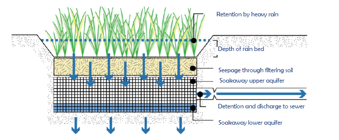
Figure: Conceptual drawing of a soakaway
A schematic drawing of a soakaway (Bioretention cell) is illustrated in the figure above. The stormwater drains from the surface and enters the soakaway at the upper vegetated layer. Then the stormwater infiltrates vertically through the soakaway and infiltrates out of the sides and bottom of the soakaway. In some cases the soakaway is not connected to any drainage network and captured runoff to the soakaway is infiltrated and in case of extreme rainfall and exceedance of its infiltration and storage capacity, storm water is surcharged to the surface. In other cases the soakaway is connected to the drainage network by a flow controlled outlet pipe as illustrated in the figure below. During extreme rainfall causing exceedance of its infiltration, storage and outlet flow capacity, the soakaway also surcharges to the surface.
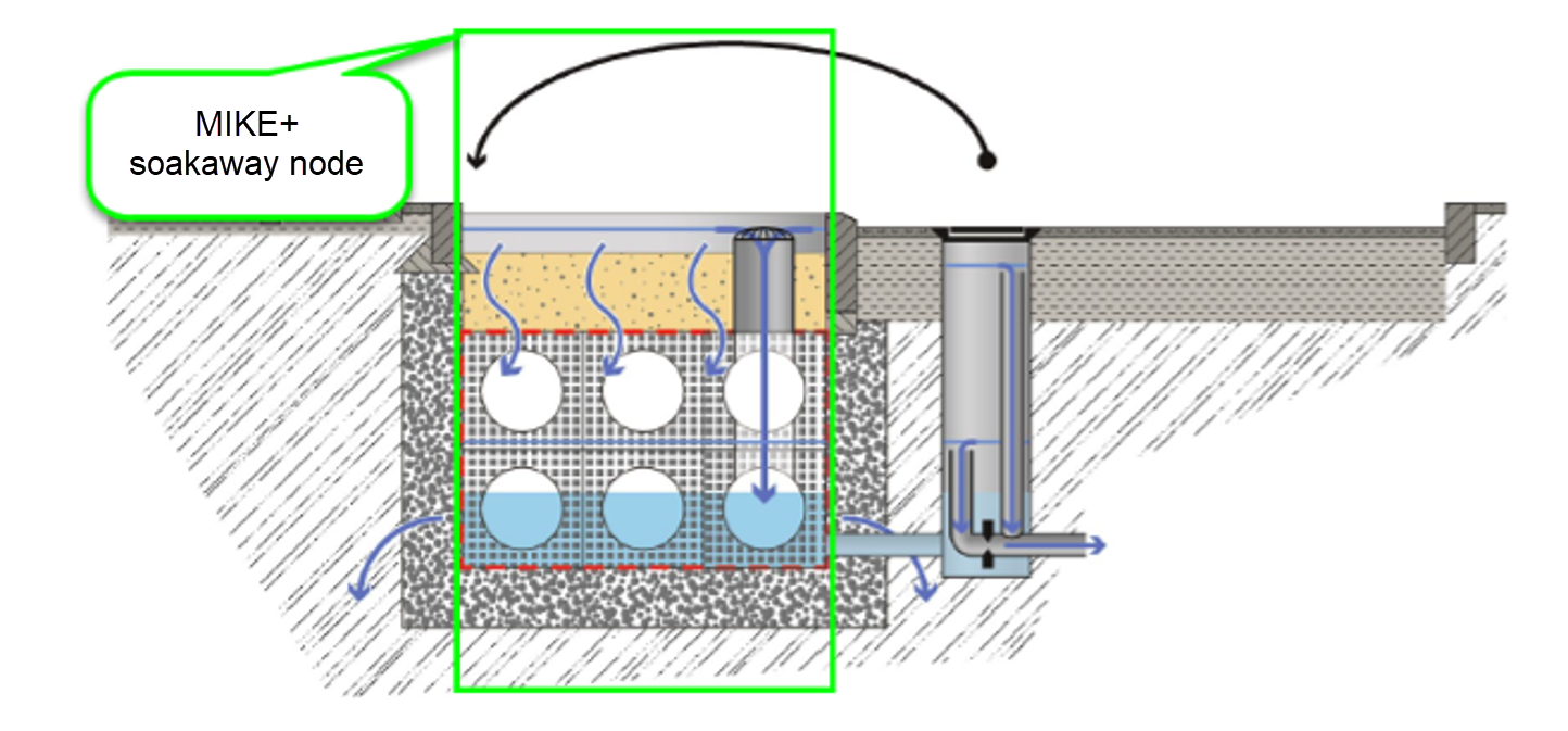
Figure: Soakaway concept in MIKE+
| Edit field | Description | Used or required by simulations | Field name in data structure |
|---|---|---|---|
| Node type | Node Types: 1. Manhole - node with shaft and chamber storage 2. Basin - node with a more complex geometry 3. Outlet - node where water leaves the system (no storage) 4. Junction - node without storage 5. Soakaway - node with a similar geometric complexity as a basin but with the features of infiltration and internal porosity. 6. River junction - node connecting one end of a collection system network to a river. | Yes | TypeNo |
| Diameter | Diameter of the manhole - not enabled for any other node types | Yes | Diameter |
| Ground level | Ground level of the node | Yes | Groundlevel |
| Bottom level | Bottom level of the manhole | Yes | InvertLevel |
| Basin geometry | Reference to a tabulated area-elevation function for the basin or soakaway geometry. The H-column for the basin geometry can start at any value, e.g. 0.0 for interpretation of H as depth in the basin. The MIKE 1D Engine will associate the first H-value to the bottom level of the node. | Yes | GeometryID |
| RiverID | The connected River ID, for a river junction node | Yes | BranchID |
| Location | The chainage location along the river, where the river junction node will discharge into the river. | Yes | BranchChainage |
Table: The edit fields in the Geometry tab (Table msm_Node)
Cover
Manholes are per default considered open at the top (Cover type equal to 'Normal'). This means, that when the water level in a manhole reaches the ground level, the water spills on the ground surface. In that case, MIKE 1D introduces an artificial reservoir on the top of the node, with a surface area 1000 times larger (by default) than the node's surface. The surcharged water is stored in the reservoir, to be returned back into the sewer. Note that this 1000 factor can be customized in the 'MIKE 1D engine configuration' dialog. The depth below ground at which this expansion starts is also controlled in the 'MIKE 1D engine configuration' dialog. A similar approach is applied for basins and soakaways except that the default expansion factor is 1, meaning that the fictive reservoir can store water even above the top of the geometry curve but keeping the storage surface unchanged (equal to the surface at the top of the geometry curve). If an expansion of the storage is expected above the geometry curve, this expansion factor should be increased in the 'MIKE 1D engine configuration' dialog. For basins and soakaways, this expansion starts at the maximum between the node's ground level and the top level of the geometry curve.
Alternatively, a ‘Sealed’ cover type can be defined, i.e. a node with a fixed lid on the top - at the ground level - so water cannot escape although the pressure still builds up inside.
The node can also be specified as a 'spilling' node (Cover type equal to 'Spilling'). In a spilling node, water escapes irreversibly from the model, if the water level reaches and exceeds the node's ground level (optionally set off by a 'buffer pressure level). The rate of spill is approximated as a free overflow over the crest at a given level and with a “conceptual” crest length. For further details, see the MIKE 1D Reference Manual.
Finally, the node can be defined with a ‘Displaceable cover’, for which the opening of the manhole gradually increases with the pressure in the node. The relationship between the node pressure and the cover’s displacement (opening) is defined with a curve of type ‘Manhole cover displacement’ in the ‘Curves and relations’ editor, where the pressure is actually defined as the difference of water column between the node and the surface. If the node is coupled to a 2D overland model, then the flow through the manhole can be two ways, i.e. the water from the 2D surface can flow back in to the drainage network. If the node is not coupled to a 2D overland model, then water can only flow from the network to the surface, after what it irreversibly leaves the model (i.e. when the manhole is fully opened, it acts a ‘Spilling’ cover with a buffer of 0)..
| Edit field | Description | Used or required by simulations | Field name in data structure |
|---|---|---|---|
| Cover type | Choose among available types: 1. Normal 2. Sealed 3. Spilling 4. Displaceable cover | Yes | CoverTypeNo |
| Buffer pressure | Buffer pressure is only active for type = spilling. Equal to the pressure above the ground level needed to cause spills from the manhole. | Yes | BufferPressure |
| Spill coefficient | Spill coefficient is only active for type = spilling or displaceable cover. Controls the spill capacity. | Yes | SpillCoeff |
| Displacement table ID | Table from the ‘Curves and relations’ editor, storing the relationship between the node pressure and the cover’s displacement (opening). Only active for type = displaceable cover | Yes | ManholeCoverDisplacementID |
Table: The edit fields in the Cover tab (Table msm_Node)
Flow regulation
'Use maximum inflow' can optionally be used to limit the inflow to the node (typically runoff from connected catchments), to describe the physical limitation of the inlet related to its size or to obstacles. When the inflow reaches the limit, the exceeding discharge is stored in a fictive reservoir above the node, and this reservoir can starts emptying into the node later when the inflow becomes lower than the specified limit. When the inflow is below the 'Maximum inflow' value, the volume stored in the reservoir is released into the node to maintain the 'Maximum inflow' rate until the reservoir has been emptied. The volume of the inflow is therefore preserved, but the inflow hydrograph is somehow delayed. The volume of water stored in this fictive reservoir can optionally be saved to the result file.
The use of a Q-H relation is only available for outlet nodes. Specifying a Q-H relation for an outlet controls the flow at the outlet. The flow (Q) value in the Q-H relation should be given as a positive value when water enters the node and a negative value for specifying a loss of water from the network model. The Q-H relation must be defined in the 'Curves and relations' editor, and with curve type 'QH relation'.
| Edit field | Description | Used or required by simulations | Field name in data structure |
|---|---|---|---|
| Use maximum flow | Activates the inlet delimiter function | Yes | InletControlNo |
| Max Inflow value | Value of maximum possible inflow into the node from runoff | Yes | MaxInlet |
| Use QH relation | When toggled on, uses Q-H tabulated function, toggled off calculates on the basis of water level. | Yes | QHTypeNo |
| QH relation ID | Reference to a tabulated QH relation | Yes | OutletQHID |
Table: The edit fields in the Flow regulation tab (Table msm_Node)
Head loss
From the 'Head loss' tab, it is possible to select which numerical method is used to compute the outlet head loss in the node. The method can be selected from the list defined in the 'Tables | Outlet Head Loss' editor, where it is also possible to edit their properties. Please refer to the 'Outlet Head Loss' chapter for more information on the individual methods.
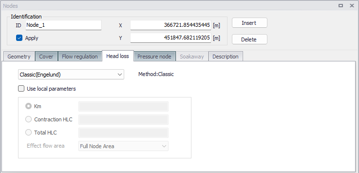
Figure: The Head Loss settings in the Nodes editor
When activating the 'Use local parameters' option, it is possible to override the settings of the selected method with values defined for the current node. When doing so, the radio button selection allows to select the loss coefficient type and value, and the 'Effect flow area' allows selecting the method for computing the effective node area.
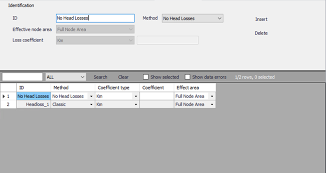
Figure: Outlet head loss editor
| Edit field | Description | Used or required by simulations | Field name in data structure |
|---|---|---|---|
| Drop-down list | Selection of the head loss calculation solution for the node | Yes | LossParID |
| Use local parameters | Enable local parameters in the node, overriding the default parameters of the selected method | Yes | LossParNo |
| Loss coefficient type radio buttons | Locally defined interpretation of head-loss coefficient. Km = "shape coefficient", Contraction HLC = outlet contraction head loss coeff. (relative to velocity head), Total HLC = outlet total head loss (relative to velocity head) | Yes | LossTypeNo |
| Coefficient value fields | Local value of loss coefficient | Yes | LossCoeffKm LossCoeffContraction LossCoeffTotal |
| Effect. flow area | Locally defined choice of method for the calculation of wetted area 1.Full Node Area 2. Calculated Effective Area 3. Reduced calculated Effective Area | Yes | EffAreaNo |
Table: The edit fields in the Head Loss tab (Table msm_Node)
Pressure node
This tab allows to declare the node as the downstream point of a pressure main's connection to the network. Manholes and basins can be declared as "Tail Node". When a node is defined as tail node, a water level (absolute elevation) needs to be specified for the "receiving node", used as lower boundary for permanently pressurized parts of the system. Please refer to the MIKE 1D Reference Manual for further information on pressure mains.
| Edit field | Description | Used or required by simulations | Field name in data structure |
|---|---|---|---|
| Pressurized tail node | When selected, defines the node in the pressure main as the downstream point of the pressure main's connection to the network. | Yes | PMTTypeNo |
| Tail level | Water level in the "receiving node". | Yes | PMLevel |
Table: The edit fields in the Pressure Node tab (Table msm_Node)
Soakaway
A soakaway is modelled as a regular basin in MIKE+, but with the difference that it includes infiltration. Its infiltration settings are defined in the 'Soakaway' tab. Since a soakaway is a regular node, it can be used in various configuration as with other node types: it can e.g. receive inflow from connected upstream pipes or discharge into downstream pipes, with or without flow regulation, be connected to weirs or orifices, etc. Soakaway nodes can also be coupled in series to support the modelling of constructed infiltration trenches. When the soakaway is connected to a downstream pipe or structure, make sure that the upstream level of this link is set correctly, and not at the bottom of the basin which is the default if no link invert level is specified. If the link is connected at the bottom, then make sure that flow regulation is applied to the out-going pipe.
The inflow to the soakaway can also be defined as for any node. It can be received from an upstream pipe, from a boundary condition to the node, or from a catchment connection that returns the catchment runoff.
The following types of infiltration are available:
- No Infiltration
- Constant Infiltration
- Infiltration
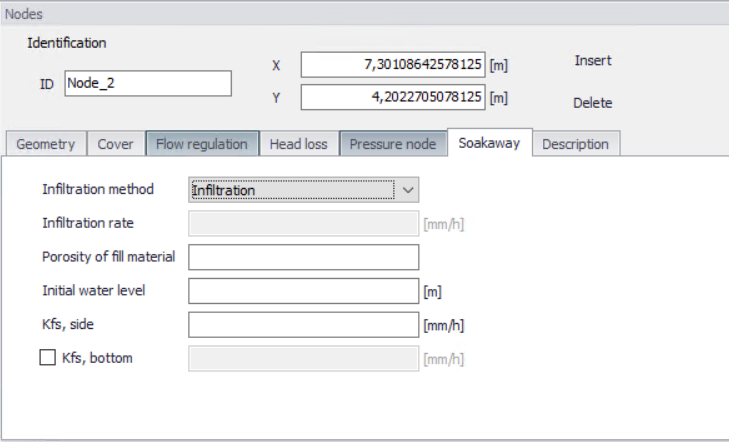
Figure: Soakaway settings in the Nodes editor
The option 'No Infiltration' is used in cases when there is no infiltration out of the soakaway. The initial water level can be set.
The 'Constant Infiltration' option provides the functionality of defining a constant infiltration rate out of the soakaway. The input required for this option is the Infiltration rate, the porosity of the fill material and the initial water level.
The 'Infiltration' option provides the functionality of having a variation in the infiltration based on the water level in the soakaway.
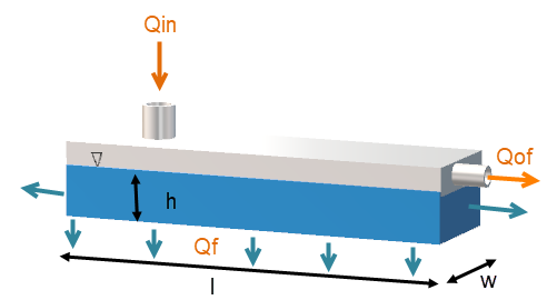
Figure: Schematic of the soakaway model
The 'Infiltration' option is based on the infiltration rate calculated by Equation (3.1) and Equation (3.2). Equation (3.1) describes the water balance of the model. Equation (3.2) and Equation (3.3) describe how the infiltration rate is calculated:
(3.1) 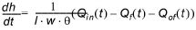
(3.2) 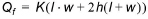
where q is the soakaway porosity and h the calculated water level.
In MIKE 1D the infiltration rate calculated by Equation (3.2) is rewritten to Equation (3.3) to be based on the basin geometry definition in MIKE+ as well as to support different hydraulic conductivity at the side and at the bottom.
(3.3) 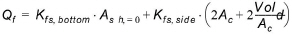
where \(K_{fs,bottom}\) is the field-saturated hydraulic conductivity at the bottom, \(K_{fs,side}\) is the field-saturated hydraulic conductivity at the side, \(A_{s}\) is the surface area and \(A_{c}\) the cross-sectional area.
The infiltration from the bottom can be turned off by a flag. However the infiltration from both side and bottom can be shut off by setting the field-saturated hydraulic conductivity to zero.
The porosity of the fill material is used to calculate the water level in the soakaway and the initial water level is used to set the initial water level in the soakaway. Table values of hydraulic conductivity, \(K_{fs}\), for different soil classes are provided in the table below. Within each soil type the hydraulic conductivity varies significantly, therefore it is important to measure the hydraulic conductivity at the site.
| Soil classification | Hydraulic Conductivity [m/s] |
|---|---|
| Gravel | 0.001 to 0.1 |
| Sand | \(10^{-5} \text{ to } 10^{-2}\) |
| Silt | \(10^{-9} \text{ to } 10^{-5}\) |
| Clay | Below \(10^{-9} \text{ to } 10^{-2}\) |
| Moraine | \(10^{-10} \text{ to } 10^{-6}\) |
Table: Hydraulic conductivity for different soil classes
| Edit field | Description | Used or required by simulations | Field name in data structure |
|---|---|---|---|
| Infiltration method | Method of infiltration | Yes | InfiltrationNo |
| Infiltration rate | Defines the infiltration rate | Yes | InfConstValue |
| Porosity of fill material | Porosity of filling material | Yes | PorosityFill |
| Initial water level | Initial water level in soakaway | Yes | InitialWL |
| Kfs, side | Conductivity of soil on the sides of the soakaway | Yes | KfsSide |
| [Tickmark] | Activates the bottom conductivity function | Yes | KfsBottomNo |
| Kfs, bottom | Conductivity of soil on the sides of the soakaway | Yes | KfsBottom |
Figure: The edit fields in the Soakaway tab (Table msm_Node)
Description
The Description tab is where free text descriptions for nodes data may be added. It offers options for providing asset and model data management information, as well as attributes for quick model data query.
| Edit field | Description | Used or required by simulations | Field name in data structure |
|---|---|---|---|
| Description | User's descriptive information related to the node | No | Description |
| Data source | Reference to an external data source (e.g. table ID) where the record has been imported from | No | DataSource |
| Asset ID | Reference to an ID used in external data sources | No | AssesName |
| Status | Data status for the entire record, serves for keeping track on the source of information | Mp | Element_S |
| Network type | Associates the node to a certain type of network. Used in cases when two or more different networks are included in the same project | No | NetTypeNo |
| Critical level | User defined critical level. Used in result presentations and in the Pump Emergency Storage Estimation analysis | Yes | CriticalLevel |
| Model | Associates the current node to a specified submodel | No | SubModelNo |
Table: The edit fields in the Description tab (Table msm_Node)