Simulation Specifications
SWMM model simulations are launched from the Simulation Setup editor, where combinations of different types of simulations may be defined.
The Simulation Setup editor has several tabs, which are relevant depending on the features and functionalities defined in the project:
- General: Includes general parameters, such as definition of the simulation period, selection of simulation types, and free text description of the simulation setup.
- Catchments: Includes parameters specific for Runoff simulation.
- HD: Includes parameters specific for HD simulation.
- Dynamic Wave: For defining parameters specific for Dynamic Wave flow routing computations.
- Water Quality: Includes parameters specific for water quality simulations.
- Events: Includes parameters for hydraulic analysis in specific periods.
- Reporting: Used for specifying results (output) to be generated by the simulation.
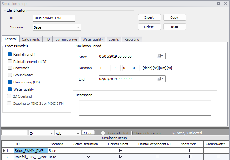
Figure: The SWMM Simulation Setup editor
The Identification group at the top and the scrollable grid table at the bottom of the editor are common across all tabs.
| Edit field | Description | Used or required by simulations | Field name in datastructure |
|---|---|---|---|
| ID | User-specified ID of simulation. ID will be reflected in the name of result files | Yes | MUID |
| Scenario | Dropdown menu for selecting ID of related Scenario for the simulation | Yes | ScenarioName |
Table: Edit fields in the Simulation Setup Identification group (mss_Project)
The following buttons are also located at the top of the editor with the Identification group:
- Insert: Inserts a new record in the Simulation Setup editor with a default unique MUID.
- Copy: Duplicates an existing (currently active) simulation setup record.
- Delete: Deletes a currently active simulation record.
- RUN: Triggers export of the current simulation job and execution of the simulation.
Note
Simulations can also be executed without opening the editor, through command lines. Refer to chapter Predefined export from command lines for more information.
General
The General tab presents parameters relevant for the simulation setup. The following parameters are specified in the General tab:
- Process Models: Define the process models to be included in the simulation.
- Simulation Period: Period covered by the simulation.
- Description: Optional description for the simulation setup.
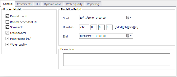
Figure: The SWMM Simulation Setup editor General tab
An overview of the editor fields and corresponding database attributes is provided in the table below.
| Edit field | Description | Used or required by simulations | Field name in datastructure |
|---|---|---|---|
| Rainfall Runoff | Surface runoff | Yes | UseRRNo |
| Rainfall Dependent I/I | Infiltration modelling | Yes | UseRDNo |
| Snowmelt | Snowmelt as part of surface runoff modelling | Yes | UseSMNo |
| Groundwater | Groundwater modelling | Yes | UseGWNo |
| Flow Routing (HD) | Network flow routing through conduits | Yes | UseFRNo |
| Water Quality | Water quality routing through conduits | Yes | UseWQNo |
| Start | Specifies start date and time for the simulation. | Yes | ComputationBegin |
| Duration | Displays the duration of the simulation in days, hours. minutes and seconds. Automatically adjusted based on Start and End time/date. May be edited, adjusting End date/time accordingly. | Yes | - |
| End | Specifies end date and time for the simulation. Adjusted automatically according to user's specification of duration. | Yes | ComputationEnd |
| Description | Free text description of the simulation setup | Optional | Description |
Table: Edit fields in the Simulation Setup General tab (mss_Project)
Catchments
The following parameters can be specified on the Catchments tab:
- Runoff Time Step: Runoff simulation time step.
- Infiltration Model: Infiltration method to use for catchments with infiltration model defined as 'Default from simulation setup'. Catchments defined with a local infiltration model can use a different model than selected in the 'Simulation setup' editor.
- Runoff Interface Files: Options for specifying the use or saving of Interface Files for the simulation.
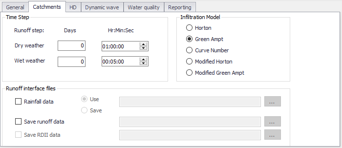
Figure: The SWMM Simulation Setup Catchments tab
| Edit field | Description | Used or required by simulations | Field name in datastructure |
|---|---|---|---|
| Time Step | |||
| Dry Weather Days Runoff Step | Time step length in days used for runoff computations (consisting essentially of pollutant buildup) during periods when there is no rainfall and no ponded water at junctions | Yes | RS_DryDay |
| Dry Weather Hr:Min:Sec Runoff Step | Time step length in hours/minutes/seconds during periods with no rainfall nor ponded water at junctions | Yes | RS_DryTime |
| Wet Weather Days Runoff Step | Time step length in days used to compute runoff from catchments during rainfall, or when ponded water still remains on the surface, or when LID controls are still infiltrating or evaporating runoff. | Yes | RS_WetDay |
| Wet Weather Hr:Min:Sec Runoff Step | Time step length in hours/minutes/seconds used to compute runoff from catchments during rainfall, or when ponded water still remains on the surface, or when LID controls are still infiltrating or evaporating runoff. | Yes | RS_WetTime |
| Infiltration Model | |||
| Horton | Horton infiltration method | No | InfiltrationModelNo |
| Green Ampt | Green-Ampt Infiltration method | No | InfiltrationModelNo |
| Curve Number | SCS Hydrology - or curve number method | No | InfiltrationModelNo |
| Modified Horton | Modified Horton infiltration method | No | InfiltrationModelNo |
| Modified Green Ampt | Modified Green-Ampt infiltration method | No | InfiltrationModelNo |
| Runoff Interface Files | |||
| Rainfall Data | Option to use or save rainfall data file | No | RainfallFileNo |
| Use | Option to read information from already created rainfall data file | Yes If RainfallFileNo = 1 | RainfallFileUseSaveNo = 1 |
| Save | Option to a Rainfall data file | Yes If RainfallFileNo = 1 | RainfallFileUseSaveNo = 2 |
| (Rainfall data file input box) | Rainfall data file name | Yes If RainfallFileNo = 1 | RainfallFileName |
| Save Runoff data | Option to save runoff data file | No | RunoffFileSaveNo |
| (Runoff data file input box) | Runoff data file name | Yes If RunoffFileSaveNo = 1 | RunoffFileSaveName |
| Save RDII Data | Option to save RDII data file | No | RDIIFileSaveNo |
| (RDII data file input box) | RDII data file name | Yes If RDIIFileSaveNo = 1 | RDIIFileSaveName |
Table: Edit fields in the Simulation Setup Catchments tab (mss_Project)
HD
The HD tab holds parameters related to hydrodynamic network computations. The parameters are organized into the following groups:
- Routing Model Settings: Parameters related to method for routing flows through the network.
- Network Interface Files: Options for specifying the use or saving of Interface Files for the network HD simulation.
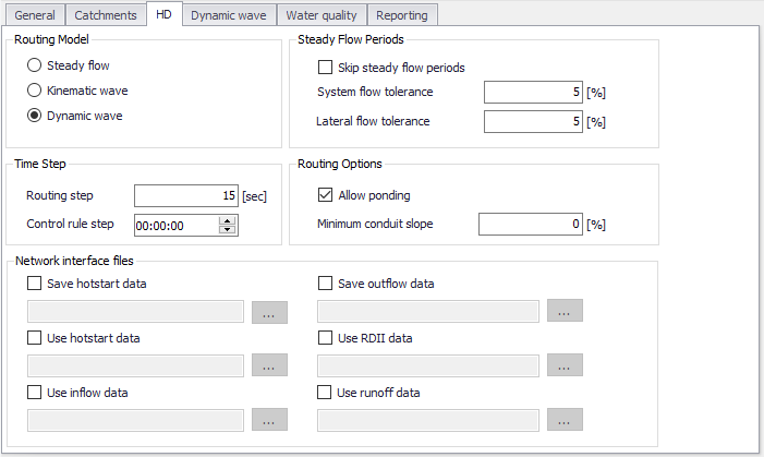
Figure: The SWMM Simulation Setup editor HD tab
| Edit field | Description | Used or required by simulations | Field name in datastructure |
|---|---|---|---|
| Routing Model | Choice of model to use for flow routing through the network: Steady Flow Kinematic Wave Dynamic Wave | Yes | RoutingModelNo |
| Routing Step | Flow routing time step | Yes | RoutingStep |
| Control Rule Step | Time step length used for evaluating control rules. A value of 0 means controls are evaluated every routing time step. | Yes If Controls are used | ControlRuleStep |
| Skip Steady Flow Periods | Option to make SWMM keep using the most recently computed conveyance system flows during identified steady flow periods instead of computing a new flow solution. Using this feature can help speed up simulation run times at the expense of accuracy. | Yes | SkipSteadyFlowPeriodNo |
| System Flow Tolerance | Threshold for percent difference between total system inflow and total system outflow used to identify steady flow periods | Yes If SkipSteadyFlowPeriodNo = 1 | SysFlowTolerance |
| Lateral Flow Tolerance | Threshold for percent differences between the current lateral inflow and that from the previous time step for all points in the conveyance system used to identify steady flow periods | Yes If SkipSteadyFlowPeriodNo = 1 | LatFlowTolerance |
| Allow Ponding | Option to allow excess water to collect atop nodes and re-enter the network when hydraulic capacity is regained. The size of the surface area for ponding is a parameter for the junction | Yes | AllowPondingNo |
| Minimum Conduit Slope | The minimum value allowed for a conduit's slope (%) | Yes | MinConduitSlope |
| Network Interface Files | |||
| Save Hotstart Data | Option to create a hotstart file from the simulation | No | HotstartFileSaveNo |
| Use Hotstart Data | Option to read information from an existing hotstart file | No | HotstartFileUseNo |
| Use Inflow Data | Option to read information from Inflow file | No | InflowFileUseNo |
| Save Outflow Data | Option to create Outflow interface file from the simulation. This file can later be used as input boundary file for a MIKE 1D simulation. | No | OutflowFileSaveNo |
| Use RDII Data | Option to read information from existing RDII interface file | No | RDIIFileUseNo |
| Use Runoff Data | Option to read information from existing Runoff interface file | No | RunoffFileUseNo |
Table: Edit fields in the Simulation Setup HD tab (mss_Project)
Dynamic Wave
Define parameters that control how the dynamic flow routing computations are made in the Dynamic Wave tab of the Simulation editor. These parameters are only relevant if the Routing Model is set to Dynamic Wave on the HD tab of the editor.
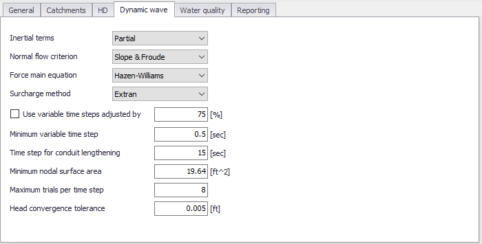
Figure: The SWMM Simulation Setup editor Dynamic Wave tab
| Edit field | Description | Used or required by simulations | Field name in data structure |
|---|---|---|---|
| Inertial Terms | Indicates how the inertial terms in the St. Venant momentum equation will be handled: None Partial Full | Yes | InertialTermNo |
| Normal Flow Criterion | Basis used to determine when supercritical flow occurs in a conduit: Slope Froude Slope & Froude | Yes | NormalFlowCritNo |
| Force Main Equation | Equation for computing friction losses during pressurized flow for conduits that have a Circular Force Main cross section: Darcy-Weisbach Hazen-Williams | Yes | ForceMainEqNo |
| Surcharge Method | Method for handling surcharge conditions: Extran Slot | Yes | SurchargeMethodNo |
| Use Variable Time Steps Adjusted By | Option to use an internally computed variable time step at each routing time period. Define the adjustment factor in the input box beside the checkbox. | Yes | VarTSAdjustBy |
| Minimum Variable Time Step | The smallest time step allowed when variable time steps are used | Yes | MinVarTS |
| Time Step for Conduit Lengthening | Time step used to artificially lengthen conduits so that they meet the Courant stability criterion under full-flow conditions (i.e., the travel time of a wave will not be smaller than the specified conduit lengthening time step). As this value is decreased, fewer conduits will require lengthening. A value of 0 means that no conduits will be lengthened. | Yes | ConduitLenTS |
| Minimum Nodal Surface Area | Minimum surface area used at nodes when computing changes in water depth. If 0 is entered, then the default value of 12.566 ft 2 (i.e., the area of a 4-ft diameter manhole) is used | Yes | MinNodalSurfaceArea |
| Maximum Trials per Time Step | Maximum number of trials that SWMM uses at each time step to reach convergence when updating hydraulic heads at the conveyance system's nodes. The default value is 8. | Yes | MaxTrialPerTS |
| Head Convergence Tolerance | When the difference in computed head at each node between successive trials is below this value the flow solution for the current time step is assumed to have converged. The default tolerance is 0.005 ft (0.0015 m). | Yes | HeadConvergenceTolerance |
Table: Edit fields in the Dynamic Wave tab of the Simulation Setup editor (mss_Project)
The available options for how inertial terms in the St. Venant momentum equation are handled are:
- None: Drops the inertial terms from the momentum equation, producing what is essentially a Diffusion Wave solution.
- Partial: Reduces the inertial terms as flow becomes critical and ignores them when flow is supercritical.
- Full: Maintains inertial terms at their full value under all conditions.
When setting how supercritical flow is identified in a conduit, the choices are:
- Slope: Water surface slope only (i.e. water surface slope > conduit slope)
- Froude: Froude number only (i.e., Froude number > 1.0)
- Slope & Froude: Both water surface slope and Froude number.
Methods for handling surcharge conditions are:
- Extran: Uses a variation of the Surcharge Algorithm from previous versions of SWMM to update nodal heads when all connecting links become full.
- Slot: Uses a Preissmann Slot to add a small amount of virtual top surface width to full flowing pipes so that SWMM's normal procedure for updating nodal heads can continue to be used.
Further details on other parameters are also found in the EPA SWMM Help document.
Water Quality
The Water Quality tab of the Simulation editor presents options for defining parameters related to pollutant buildup/washoff processes when simulating water quality.
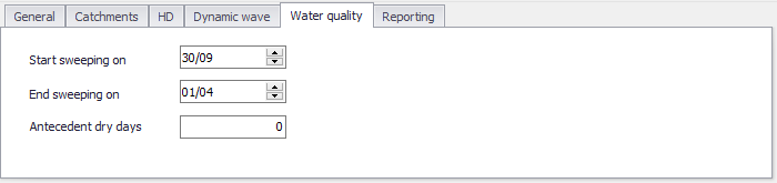
Figure: The Water Quality tab page in the Simulation Setup editor
| Edit field | Description | Used or required by simulations | Field name in data structure |
|---|---|---|---|
| Start Sweeping On | Day of the year (day/month) when street sweeping operations begin | Yes | StartSweep |
| End Sweeping On | Day of the year (day/month) when street sweeping operations end | Yes | EndSweep |
| Antecedent Dry Days | The number of days with no rainfall prior to start of the simulation. Value used to compute an initial buildup of pollutant load on catchments | Yes | AntecedentDryDay |
Table: Edit fields in the Water Quality tab of the Simulation Setup editor (mss_Project)
Events
Events are optional periods of time, limiting the periods during which the full unsteady hydraulic analysis of the network is made. The purpose of only computing hydraulics for particular events is to speed up long-term simulations when only some periods of time within these simulations are of interest (typically e.g. due to significant rain intensity and drainage flows).
If this table is left empty, the simulation is run using the full unsteady hydraulic calculation during the entire simulation period.
If one or more events (i.e. limited time periods) are listed on the table, then the full unsteady hydraulic analysis is performed only during these events. For times outside of these events, the hydraulic state of the network remains the same as it was at the end of the previous event. Although unsteady hydraulic calculations are restricted to these events, a full accounting of the hydrology is still computed over the entire simulation period. During inter-event periods, any inflows to the network from runoff, groundwater flow, dry weather flow, etc., are ignored.
The 'Insert' and 'Delete' buttons to the right of the table are used to add and remove events from the list. For each event, the following properties are required:
- Start time: The date and time of the start of the event.
- End time: The date and time of the end of the event.
- Include: A check box controlling whether the event is used or not. The event is used in the simulation (with full unsteady hydraulic analysis) only if it's ticked, whereas it will be ignored when unticked.
Note
When a new event occurs, the water in storage unit nodes will remain at the same levels it had at the end of the previous event. Therefore, one may want to choose event intervals long enough to minimize the effect that storage carryover might have.
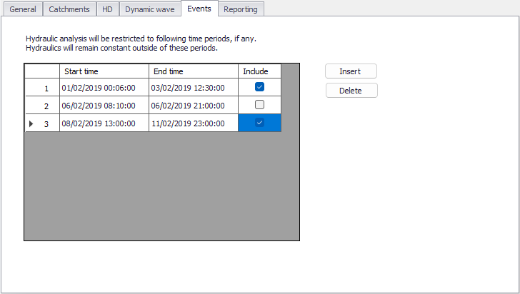
Figure: The Events tab from the SWMM Simulation setup editor
Reporting
The Reporting tab presents options for saving detailed time series results in individual subcatchments, nodes, and links. The dialog organizes information into the following groups:
- Reporting Period: For defining the period over which reporting of simulation results is done.
- Summary Specification: For defining items to be included in a simulation summary.
- Subcatchments Detailed Report: Option for generating detailed results for all/selected catchments.
- Nodes Detailed Report: Option for generating detailed results for all/selected nodes.
- Links Detailed Report: Option for generating detailed results for all/selected links.
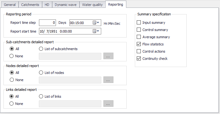
Figure: The SWMM Simulation Setup Reporting tab
Reporting Period
Define the reporting frequency and period under the Reporting Period group.
| Edit field | Description | Used or required by simulations | Field name in data structure |
|---|---|---|---|
| Report Time Step | Report saving time step (in Days and Hr:Min;Sec) | Yes | Report_Timestep |
| Report Start Time | Date and time of day when reporting of simulation results commence | Yes | Report_StartTime |
Table: Edit fields in the Reporting Period group (mss_Project)
Summary Specification
| Edit field | Description | Used or required by simulations | Field name in data structure |
|---|---|---|---|
| Input Summary | To include a summary of input data in the output report | No | ReportInputNo |
| Control Summary | To include a summary of the control data in the output report | No | ReportControlNo |
| Average Summary | To report the average of the results for all routing time steps in a reporting time step instead of the instantaneous results that occur at the end of the reporting time step | No | ReportAverageNo |
| Flow Statistics | Specifies whether or not summary flow statistics should be reported or not | No | FlowStatsNo |
| Control Actions | Specifies whether or not summary of control actions taken during simulation should be listed or not | No | ControlsNo |
| Continuity Check | Specifies whether or not summary of continuity checks should be reported or not | No | ContinuityNo |
Table: Edit fields in the Reporting tab page Summary Specification group (mss_Project)
Subcatchments Detailed Report
| Edit field | Description | Used or required by simulations | Field name in data structure |
|---|---|---|---|
| All, None, or List of Subcatchment | Options for which catchments detailed results are generated | Yes | SubCatchmentsNo |
| List of Subcatchments | Specify a catchment selection list | Yes If SubCatchmentsNo = 2 | SubCatchmentsFileName |
Table: Edit fields in the Reporting tab page Subcatchments Detailed Report group (mss_Project)
Nodes Detailed Report
| Edit field | Description | Used or required by simulations | Field name in data structure |
|---|---|---|---|
| All, None, or List of Nodes | Options for which nodes detailed results are generated | Yes | NodesNo |
| List of Nodes | A nodes selection list is expected | Yes If NodesNo = 2 | NodesFileName |
Table: Edit fields in the Reporting tab page Nodes Detailed Report group (mss_Project)
Links Detailed Report
| Edit field | Description | Used or required by simulations | Field name in data structure |
|---|---|---|---|
| All, None, or List of Links | Options for which links detailed results are generated | Yes | LinksNo |
| List of Links | Define a links selection | Yes If LinksNo = 2 | LinksFileName |
Table: Edit fields in the Reporting tab page Links Detailed Report group (mss_Project)