Controlling the LTS Computations
In addition to data and parameters supplied through the general model setup and LTS editors, several engine parameters are available for controlling and adjusting the default performance of the LTS computation.
These parameters can be accessed through the 'MIKE 1D engine configuration' dialog, from the 'Simulation' tab in the ribbon.
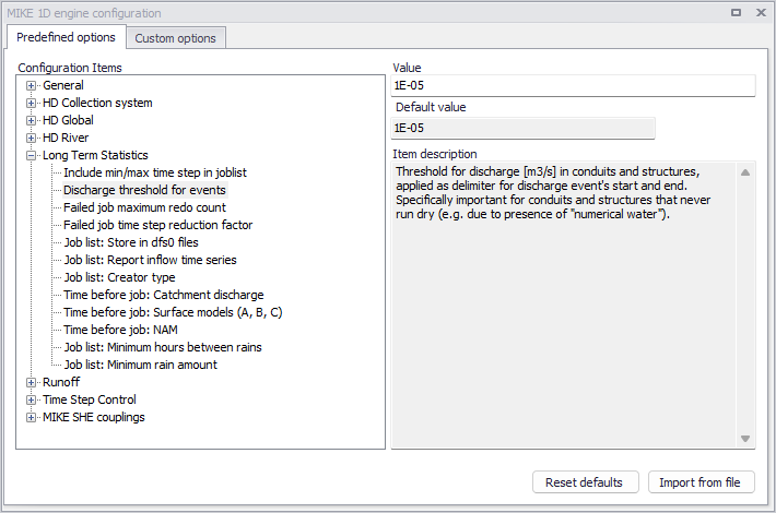
Figure: LTS engine parameters can be modified through "MIKE 1D engine configuration"
Include min/max time step in joblist
When Include min/max time step in joblist is "ON", the job list generator will include lines with minimum and maximum timestep in each simulation event definition (see example below):
[SIMULATION_EVENT]

      Simulation_start = '1933-07-22 16:31:00'

      Simulation_end = '1933-07-22 18:49:00'

      Simulation_end_no_duration = '1933-07-22 18:39:00'

      Hotstart_file = 'Hot_startLTSBase.res1d'

      Hotstart_time = '2019-01-01 16:31:00'

     Hotstart_hydrological_inflow = 0.0

      Duration = '02:18:00'

     Job_number = 1

      Job_start_criterion = 'JL_Criterium_1'

      Job_stop_criterion = 'JL_Criterium_2'

     DtMin = 10.0

     DtMax = 10.0

EndSect  // SIMULATION_EVENT
By "manually" editing these parameters for individual simulation events, user can ensure that e.g. a particularly difficult rain event is simulated with shorter time steps than generally specified.
Possible values:
- On: writes DTmin and DTmax in the job list
- Off: does not write DTmin and DTmax in the job list.
Discharge threshold for events
This parameter controls the definition of statistical intermittent events for accumulated variables (discharge, mass transport) in network conduits.
Per definition, discharge and mass transport events (duration, volume and accumulated mass) are delimited by the events start time and end time.
Due to "numerical water" in empty conduits, discharge and, possibly, mass transport is never zero during a simulation. Accordingly, without a specified threshold discharge (or specified very low, i.e. smaller than expected "numerical" discharge), every simulated accumulated event in a conduit would have duration equal to the simulation period, and the accumulated volume and/or mass would include numerical water and mass. The two consecutive discharge events, even they are sufficiently separated (dT > Interevent dT) would be reported as a single event. The effect of correctly/incorrectly specified LTS_DISCHARGE_THRESHOLD is illustrated in the figure below.
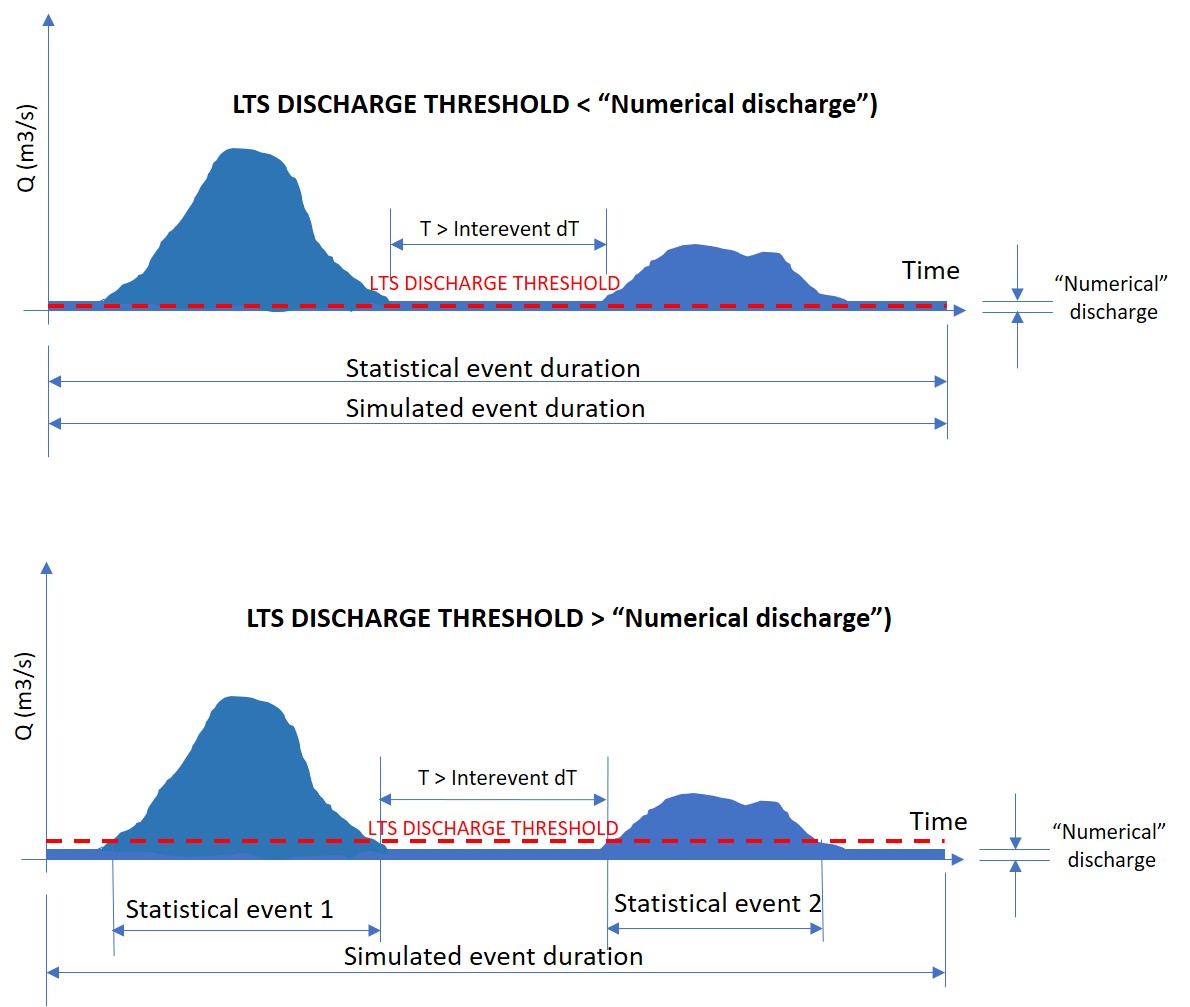
Figure: LTS discharge threshold
Possible values are any positive value.
Failed job maximum redo count
This parameter is related to the automatic recovery of failed jobs during a LTS simulation. It specifies how many times a failed job may be re-simulated with a shorter time step.
Possible values are integer values equal to or higher than 0.
Note
Time step for a LTS simulation should be specified so to ensure a stable and accurate simulation of the most intensive events included in the LTS simulation. Re-simulating accidentally failed jobs with a shorter time step should be considered as exception.
Failed job time step reduction factor
Likewise LTS_FAILED_JOB_MAX_REDO_COUNT, this parameter is related to the automatic recovery of failed jobs during an LTS simulation. It specifies how much the simulation time step shall be reduced in the following attempt to simulate a failed job..
Possible values: 0 < Failed job time step reduction factor < 1
Job list: Creator type
This parameter controls the process of job list creation, with focus on speed or accuracy.
Choice of possible values (0 or 1) has the following effects:
- LTS_JOBLIST_CREATOR_TYPE = 0: Calculates the inflows used by job list criteria only when it is raining. This effectively skips potential jobs where boundary inflow other than rainfall satisfies a job start condition, but there is no active rain. This contributes to the job list creation efficiency, as wet periods typically represent a smaller part of the simulated period.
- LTS_JOBLIST_CREATOR_TYPE = 1: Calculates the inflow continuously, i.e. also during periods without rainfall. This option is relevant in cases when the model includes significant intermittent inflows which are not directly related to the local rainfall. This slows down the process of job list creation.
Possible values:
- 0: calculates inflow only during rain
- 1: calculate inflows continuously.
Job list: Store in dfs0 files
When this parameter is set to "On", the LTS job list creation process generates a *JobStartEnd.dfs0 file containing the following time series items:
- Job ON/OFF [-]: 1 (job = ON); 0 (job = OFF)
- Duration [hours]: Simulation job duration.
An example of such file shown in figure below:
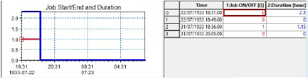
Figure: Example of dfs0 file containing time series of job activity and duration
Possible values:
- On: create .JobStartEnd.dfs0 file
- Off: do not create .JobStartEnd.dfs0 file.
Job list: Report inflow time series
When this parameter is set to "On", the LTS job list creation process generates a *BaseJobCriteriaInflow.dfs0 file containing the time series of inflows into the system, used in the evaluation of job list criteria, i.e. the file includes as many time series as there are job list criteria in the actual LTS setup.
The time series are created by summing up all inflows (catchment discharges, runoff, infiltration, any other lateral inflow) connected to the specific location (Individual), part of the system (List, defined by a selection) or to the whole system (General).
The figure below illustrates example with two job list criteria. The time series are intermittent, i.e. only contain inflow discharges for the period during the simulation jobs.
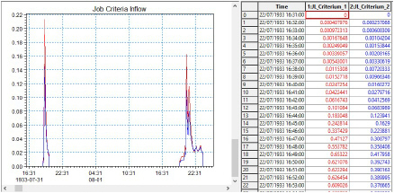
Figure: Example of dfs0 file with inflow time series associated with two job list criteria
Possible values:
- On: create .BaseJobCriteraInflow.dfs0 file
- Off: do not create .BaseJobCriteraInflow.dfs0 file.
Time before job: Catchment discharge
This parameter controls the running of catchment discharge model in the dry periods between simulated events, during a "live" run of catchment and network model in an LTS simulation.
When running the catchment discharge model (typically generating wastewater inputs to the network) and the network model simultaneously in an LTS simulation, the catchment discharge model may be set to run only during the network simulation, or it can be specified to start running several days before the start time of the network simulation. Ultimately, the catchment discharge model can be set to run continuously.
Purpose of stopping the catchment discharge simulation between LTS simulation events is to minimize the simulation time and size of the catchment discharge result file. As catchment discharge establishes instantaneously, default setting is "0", i.e. the catchment discharge simulation will start exactly at the same time as the network simulation.
Possible values:
- -1: catchment discharge simulation runs continuously between events
- 0: catchment discharge simulation starts at the same time as network simulation catchment
- N (1,2,3,…): discharge simulation starts N days before the network model simulation.
Time before job: NAM
This parameter controls the running of RDII (NAM) hydrological model in the dry periods between simulated events, during a "live" run of catchment and network model in an LTS simulation.
When running the RDII hydrological model (generating continuous hydrological inputs to the network) and the network model simultaneously in an LTS simulation, the RDII model may be set to start running a number of days before the network simulation or, ultimately, the RDII model can be set to run continuously. The latter option is preferred, because RDII model simulates slow hydrological processes and only a continuous simulation between LTS events ensures correct results..
Possible values:
- -1: RDII simulation runs continuously between events
- 0: RDII simulation starts at the same time as network simulation
- N (1,2,3,…): RDII simulation starts N days before the network model simulation.
Time before job: Surface models (A, B, C)
This parameter controls the running of any surface runoff model in the dry periods between the simulated events, during a "live" run of catchment and network model in an LTS simulation.
When running a surface runoff model (typically generating storm runoff inflows to the network) and the network model simultaneously in an LTS simulation, a surface runoff model may be set to run only during the network simulation, or it can be specified to start running a number of days before the start time of the network simulation. Ultimately, the surface runoff model can be set to run continuously.
Purpose of stopping a surface runoff simulation between LTS simulation events is to minimize the simulation time and size of the runoff result file. However, this must be done with a due care to avoid incorrect simulation. Models involving processes which depend on significant "hydrological memory" (e.g. infiltration) may need to be run before the actual start of the network simulation, in order to capture the effects of small rainfall events not included in the LTS job list. .
Possible values:
- -1: Surface runoff simulation runs continuously between LTS events
- 0: Surface runoff simulation starts at the same time as network simulation
- N (1,2,3,…): Surface runoff simulation starts N days before the network model simulation.
Job list: Minimum hours between rains
This parameter allows to consider consecutive recorded rainfalls, separated by relatively short dry intervals, as one continuous rainfall event. This may affect the start time of an LTS job (it is set to the rainfall start time) in cases when a rainfall event included in the LTS job list is preceded by a small, low-intensity rainfall. This is illustrated in figures below.
If the preceding small rainfall is separated from a large rainfall event by a dry interval longer than the specified Job list: Minimum hours between rains , the two rainfalls are considered as two separate events. The small rainfall is ignored as it generates the inflow to the system smaller than the threshold specified by any of the job list START criteria. The big rainfall is included in the job list (it exceeds the threshold discharge for the time longer than the specified duration, for at least one of the job list START criteria. The start time for the simulation is set to the start of the big rainfall event.
The end of the job list event is set to the time when the inflow drops below the specified threshold for the time longer than the specified duration, for all specified job list STOP criteria.
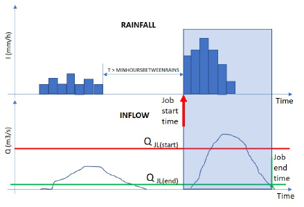
Figure: Definition of event start for rainfall events separated by a long dry interval
If the preceding small rainfall is separated from a large rainfall event by a dry interval shorter than the specified Job list: Minimum hours between rains, the two rainfalls are considered as one continuous event. The small rainfall is included in the simulation, as it is treated as part of the big event. The joint rainfall event is included in the job list (it exceeds the threshold discharge for the time longer than the specified duration, for at least one of the job list START criteria. The start time for the simulation is set to the start of the joint rainfall event, effectively at the beginning of the small rainfall.
The end of the job list event remains unaffected, it is set to the time when the inflow drops below the specified threshold for the time longer than the specified duration, for all specified job list STOP criteria.
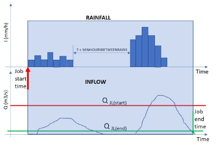
Figure: Definition of event start for rainfall events separated by a short dry interval