Location of structures in 2D domain
Weirs, culverts, and dikes locations are defined as line sections. The location in the domain of a line section is given by a number of geo-referenced points which together make up a polyline. This is illustrated in the figure below. The polyline defines the width of the cross section perpendicular to the flow direction. A minimum of two points is required. The polyline is composed of a sequence of line segments. The line segments are straight lines between two successive points. The polyline (line section) in the numerical calculations is defined as a section of element faces. The face is included in the section when the line between the two element centers of the faces crosses one of the line segments. If two faces in a triangular element are part of the same face section, the face section is corrected so that these two faces are excluded from the face section and instead the third face in the triangle is applied. The left and right side of the of the line section is defined by positioning at the start point and looking forward along the cross-section.
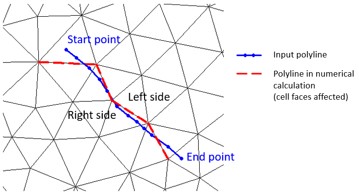
Figure: The location of a line section
To ensure a proper mapping simply extend the polyline defining the structure location so that it intersects a line segment connecting cell mid-points, as defined in the figure below.
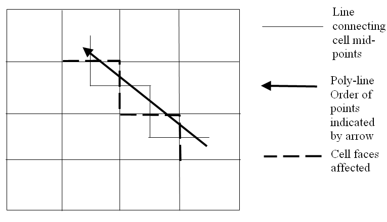
Figure: Definition of cell mid-points