Optimization - Pump and Valve Scheduling
The purpose of this optimization-based tool is to support scheduling of pumps and operation of control valves. The optimization is based on optimization algorithms that can run with any extended period analysis model.
These two algorithms are available:
- SCE: The Shuffled Complex Evolution (SCE) method is a global optimization algorithm that combines various search strategies, including (i) competitive evolution, (ii) controlled random search, (iii) the simplex method, and (iv) complex shuffling.
- DDS: The Dynamically Dimensioned Search algorithm (DDS) is an optimization algorithm designed for large set of parameters. It automatically scales the search to find good solution within the maximum number of model calls. The algorithm starts to search globally, and then becomes more local as the number of models call approaches the maximum allowable number. Candidate solutions are created by perturbing the current values in the randomly selected dimensions only. The dimension of search is automatically adjusted.
The optimization setup includes "Controls" and "Targets". Controls are valves and pumps, and their operations and Targets are goals such as requested water levels or flows, pressures, etc.
Controls and their operations may be:
- Pump ON/OFF versus time (hourly basis)
- Pump ON/OFF defined as a repeating pattern (hourly basis)
- Pump speed versus time (hourly basis)
- Valve opening % versus time (hourly basis)
- Valve flow set-point versus time (hourly basis)
Targets are:
- Water level in a tank/reservoir (last value, minimum, maximum, average, span, time series)
- Water quality at a node (junction, tank)
- Total volume or a volume difference in a tank/reservoir (can be translated to the water level)
- Maximum or average or total flow across a valve
- Pump power
- Pump energy costs
- Source water balance (e.g. 60% of total water from a source 'A' and 40% of a total water flow from a source 'B')
The Optimization dialog box is reached by selecting 'Model type' from 'General Settings' from the Setup tree and then by selecting the 'Optimization' option. Once selected, the Optimization is added to the Special analyses group in the Setup tree.
Methods
A list of the Optimization window's attributes follows with a short description given for each one.
The list of optimization configurations is controlled with the following buttons:
- Insert: This button is used to insert a new Optimization into the list.
- Delete: This button is used to delete an Optimization from the list.
- Run: This button is used to run the simulation for the active Optimization in the list.
- Stop: This button is used to stop (cancel) the optimization that is currently running.
- Report: This button is used to report the optimization results. See the chapter Report for more information.
Note
It is possible to insert multiple optimization analyses, each with its own settings, and then run the selected optimization by selecting it from the list. This is convenient when you need to investigate various optimization settings or different control strategies.
DDS Optimization method settings
Settings for the DDS optimization method are:
- Maximum number of calls: This data entry is one of the stop criteria and it is the maximum number of model call during the optimization process. If the maximum number of model calls is reached, the optimization process will stop, and it will report the best solution that was found.
- Optimizer seed: This data entry is used to initiate random number generator. There is no need to change the entry except in special cases.
- Setpoint target objective: This data entry defines another stop criteria that compares the actual value of the objective function and it stops when its value is below this data entry.
- Use maximum run time per simulation: This data entry can be used in special cases when the hydraulic simulation due to the “random” choice of control variables by the optimizer might take exceptionally long time to finish. In such case, if this criterion is used, the program will cancel the hydraulic simulation and it will use a high penalty for its settings for the optimizer.
- Use maximum number of invalid solutions per simulation: This data entry can be used in special cases when the hydraulic simulation due to the “random” choice of control variables by the optimizer results in unbalanced or hydraulically unstable conditions during the extended period simulation run. In such case, if this criterion is used, the program will cancel the hydraulic simulation and it will use a high penalty for its settings for the optimizer.
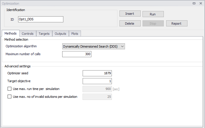
Figure: DDS Optimization settings
SCE Optimization method settings
Settings for the SCE optimization method are:
- Maximum number of calls: This data entry is one of the stop criteria and it is the maximum number of model call during the optimization process. If the maximum number of model calls is reached, the optimization process will stop, and it will report the best solution that was found.
- Number of complexes: This data entry defines the number of complexes (p) used in the optimization process. It is used to calculate the initial population (number of different model setups to run). The population size is s = p x m.
- Number of points in each complex: This data entry defines the number of points in each complex (m) used in the optimization process. It is used to calculate the initial population (number of different model setups to run). The population size is s = p x m.
- Minimum number of complexes: The minimum number of complexes is required when the number of complexes is reduced during the optimization.
- Number of evolution steps: This data entry defines the number of evolution steps taken by each complex before complexes are shuffled.
- Number of points in each sub-complex: This data entry defines the number of points in each sub-complex.
- Optimizer seed: This data entry is used to initiate random number generator. There is no need to change the entry except in special cases.
- Target objective: This data entry defines another stop criteria that compares the actual value of the objective function and it stops when its value is below this data entry.
- Maximum loops of convergence: This data entry defines the maximum number of loops used in the optimization.
- Minimum relative change in convergence function: This data entry is another stop criteria where solutions are compared in terms of a change in the objective function and the optimization stops when there is no improvement.
- Use maximum run time per simulation: This data entry can be used in special cases when the hydraulic simulation due to the "random" choice of control variables by the optimizer might take exceptionally long time to finish. In such case, if this criterion is used, the program will cancel the hydraulic simulation and it will use a high penalty for its settings for the optimizer.
- Use maximum number of invalid solutions per simulation: This data entry can be used in special cases when the hydraulic simulation due to the "random" choice of control variables by the optimizer results in unbalanced or hydraulically unstable conditions during the extended period simulation run. In such case, if this criterion is used, the program will cancel the hydraulic simulation and it will use a high penalty for its settings for the optimizer.
- Use hotstart file: This data entry can be used to start the new optimization run from the results of the previous optimization run. Select the file with the extension .dat that contains the optimization results.
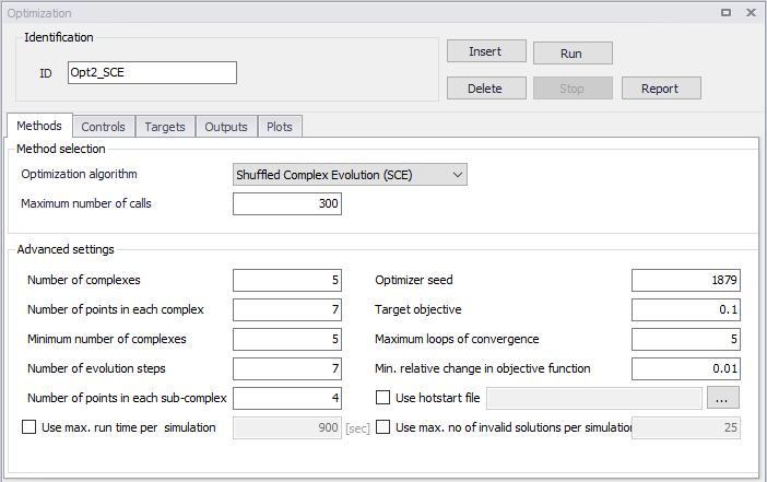
Figure: SCE Optimization settings
Controls
These settings define Controls such as valves and pumps, and their operations. A list of the control settings follows with a short description given for each one. Multiple controls can be entered in this dialog box.
- Control ID: This data entry is used to identify the control.
- Is active: This check box allows the user to toggle the Active status of the control on and off. The simulations will omit all controls that are not active.
- Controlled link type: This data entry defines the type of the controlled link, the following options are available:
- Pump ON/OFF or relative speed
- Valve settings
- Controlled link ID: This is the ID of the controlled link.
- Control type: This data entry defines the how the link will be operated, the following options are available:
- Pattern (decisions about the link operation will be based on a repeating pattern)
- Time levels (decisions about the link operation will be based on predefined time levels)
- Clock time (decisions about the link operation will be based on predefined clock time levels)
- Pattern length: This data entry is used when the Control type is 'Pattern'. It is the length (duration) of the repeating pattern that will be used for the link operation. A typical entry is 24 (hours).
- Minimum decision interval: This data entry is used when the Control type is 'Pattern'. It is the minimum time step of the repeating pattern that will be used for the link operation. A typical entry is 1 (hour).
- Optimization set-point table: This data entry is used when the Control type is 'Time levels' or 'Clock time'. It is the name of the time series curve that defines the time levels when the decision will be made for the link operation.
- Description: This data entry is for the user defined description of the control.
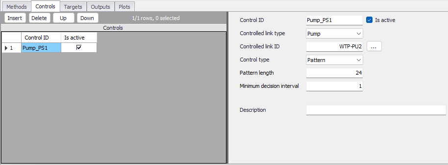
Figure: Optimization controls settings
Targets
These settings define Targets that are goals such as requested water levels or flows, pressures, etc. A list of the settings follows with a short description given for each one. Multiple targets can be entered in this dialog box.
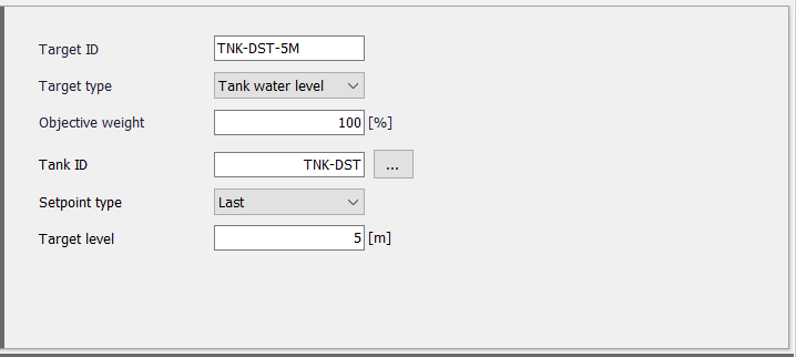
- Target ID: This data entry is used to identify the target.
- Is active: This check box allows the user to toggle the Active status of the target on and off. The simulations will omit all targets that are not active.
- Target type: This list defines the type of a target, the following options are available:
- Tank water level (depth of water in the tank)
- Water quality
- Pressure (junction pressure)
- Flow (link flow)
- Pump power (optimization pumps or all pumps)
- Pump energy costs (optimization pumps or all pumps)
- Source water balance (% of water supplied from a tank/reservoir)
- Objective weight: This data entry is used to specify the weight of this target. Use different number if you want to prioritize one target over another).
- Tank ID: This data entry is for entering the ID of the target tank (when the target type = tank water level)
- Junction ID: This data entry is for entering the ID of the target junction (when the target type = pressure)
- Link ID: This data entry is for entering the ID of the target link (when the target type = flow)
- Water balance definition: This table is for entering the list of water sources and their water supply percentages (when the target type = source water balance). Note, that the data entry here is the outlet pipe from a storage tank and not the storage tank. That is in case that the storage tank have multiple outlets and some are feeding different zones or parts of the water supply system.
- Setpoint type: This list defines the set-point type. The following options are available:
- Last (this is the value at the end of the simulation)
- Minimum (this is the minimum value during the simulation)
- Maximum (this is the maximum value during the simulation)
- Average (this is the average value during the simulation)
- Span (this is the difference between the minimum and maximum value during the simulation).
- Target level: This data entry is used to define the target set-point value.
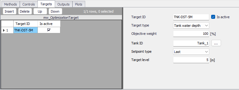
Figure: Optimization targets settings
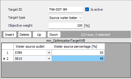
Figure: Inputs for Source water balance
Outputs
Outputs provides a list of computed controls and their optimized settings and a summary of targets with requested and computed values.
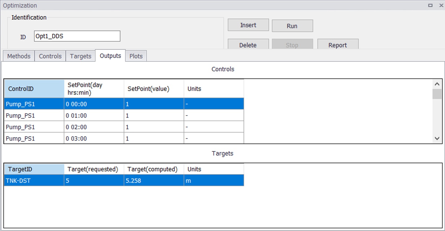
Figure: Optimization outputs
In addition to this summary, it is always possible to use the standard time series plots to select a target storage tank, for example, and plot the time series of the computed water level to see its full time history.
Plots
Plots provides time series graphs with computed controls and their optimized settings.
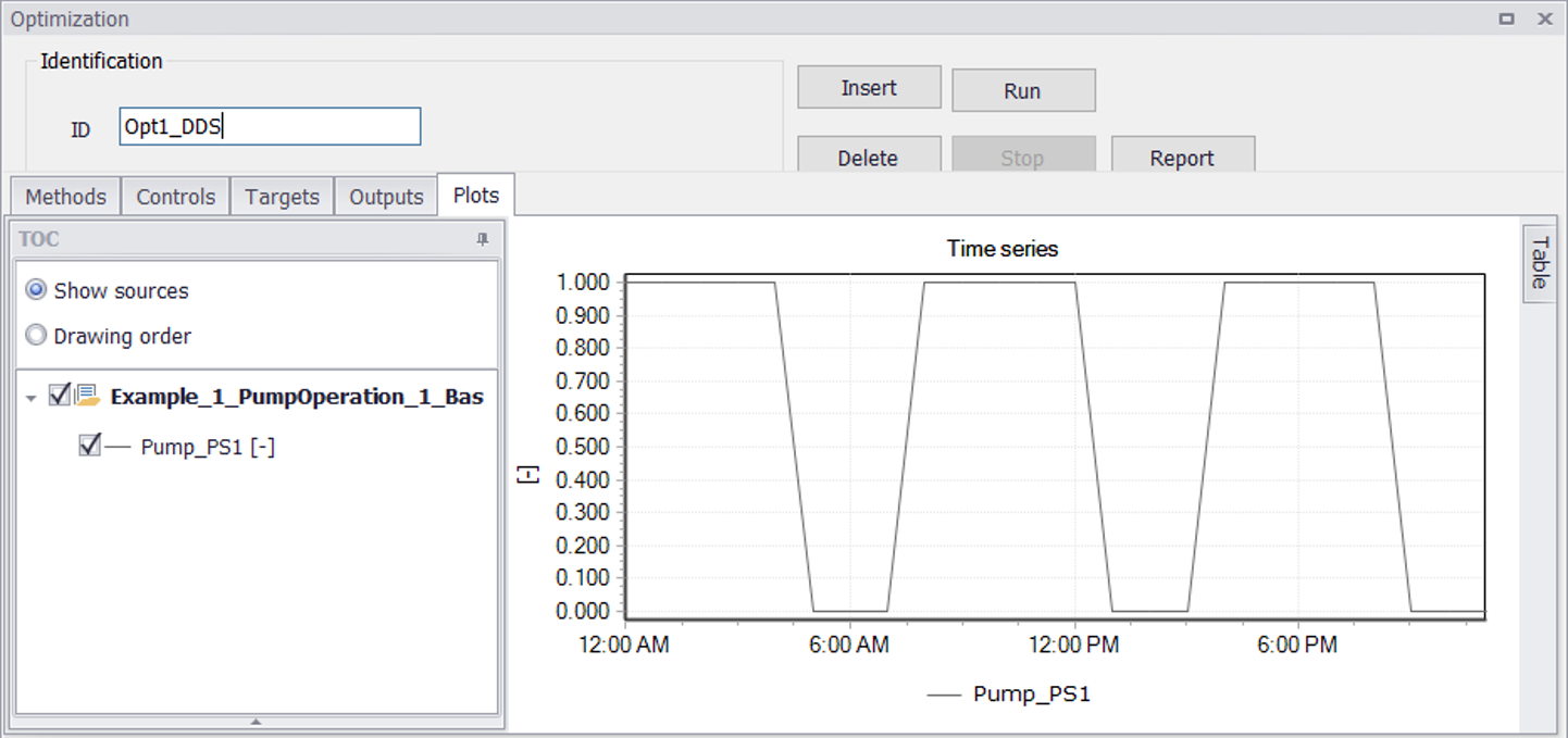
Figure: Optimization plots
Report
Report provides a HTML version of the outputs, i.e. a list of computed controls and their optimized settings and a summary of targets with requested and computed values.
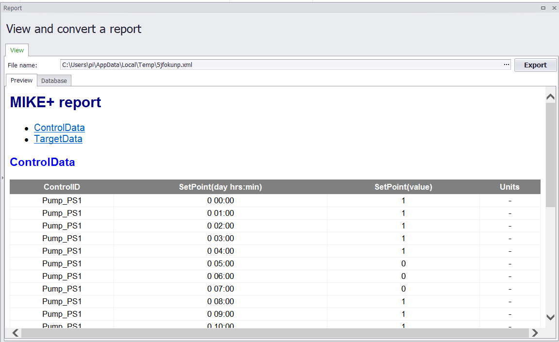
Figure: Optimization report
Examples
Several examples are provided here to illustrate how controls and targets can be defined.
Example 1 - Pump control
The system contains a pump and a storage tank that is receiving the pumped water. The storage tank has also outlets that are supplied by gravity. The goal of the optimization is to find a pump operating strategy that will maintain the water level at the end of the simulation at 5m.
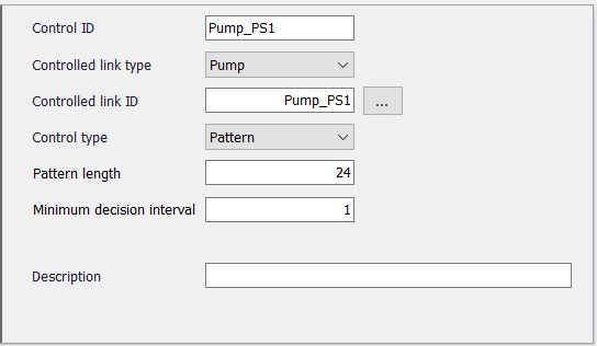
We will enter the pump into Controls:
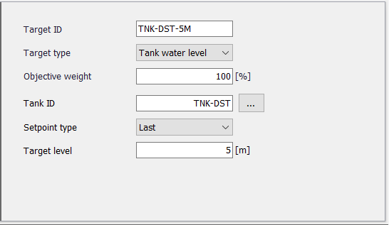
And we will enter the storage tank level into Targets:
Example 2 - Valve control
The system contains a gravity transmission pipeline and a downstream storage tank that is receiving the water. There is an inlet gate valve for the storage tank. The storage tank has also outlets that are supplied by gravity. The goal of the optimization is to find an operating strategy that will maintain the water level at the end of the simulation at 5m.
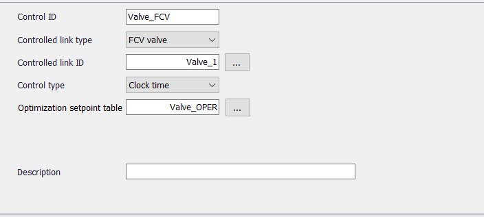
We will enter the flow control valve into Controls:
The valve set-point table for the decision levels could look something like this:
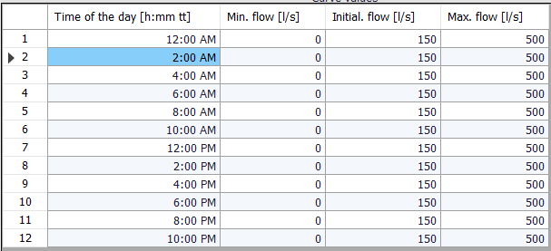
These are the decision levels i.e. time levels when the valve settings can change. The minimum and maximum values are used to define the range within which the flow control valve can operate, and the initial value is the initial valve setting.
And we will enter the storage tank level into Targets: