Create Flood Raster Tool
Introduction
The purpose of the 'Create flood raster' tool is to map 1D and/or 2D flood level results onto a DEM with a more detailed spatial resolution, to create a detailed and unified map of water depths.
The tool uses time-varying input results and gets the maximum water level from them, in order to return a raster with a single time step containing the maximum water depth.
1D results are mapped using interpolation along the river line. Refer to the MIKE 1D Reference Manual for more information about the interpolation methods.
2D water level results are considered uniform within each mesh element / cell. Each cell's water level is compared to ground levels from the DEM in the extent of the cell to compute the water depths (no spatial interpolation of raw water levels takes place).

Figure: Comparison of original 2D flood depth results (left) and resulting raster (right)
The tool offers various options to control how 1D and 2D results are e.g. interpolated and combined together.
It is accessed from the 'Results' tab of the ribbon.
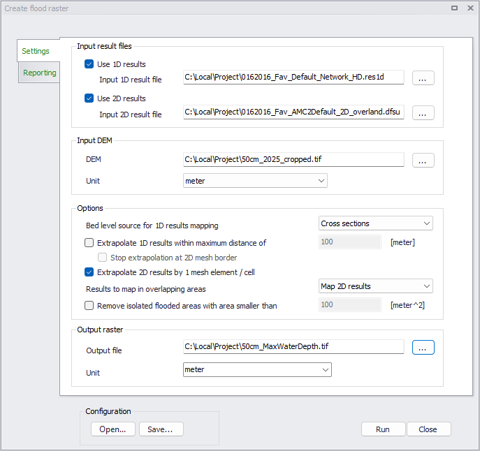
Figure: The 'Create flood raster' tool window
Input result files
Selection of results data is made in the 'Input result files' group:
- 1D results: the path to the input 1D river result file. The selected file must contain the water level result item. Using a 1D result file is optional, and may be ignored if only 2D results are to be mapped.
- 2D results: the path to the input 2D overland result file. Both files in .dfsu and .dfs2 format are supported. The selected file must contain the water level result item. Using a 2D result file is optional, and may be ignored if only 1D results are to be mapped.
Note
The tool is designed for 1D river model and will map water levels from all links in the 1D result file. If the model network also includes a Collection System network, pipes and natural channels may also be mapped when their water level is higher than the ground levels from the DEM. If this is unexpected, it is recommended to save a result file included only the links to be mapped, during the simulation.
Input DEM
A DEM must always be selected, and must be in the same map projection as the input result files. Both .tif and .dfs2 file formats are supported.
The DEM's grid controls the grid of the output raster file: this output raster will get the same cell size, number of cells and coordinates as the DEM.
When the DEM is provided as a .tif file, the unit of its ground level values must also be selected from the corresponding drop-down list. When the DEM is provided as a .dfs2 file, the unit is obtained from the file's properties directly.
Options
The options below allow to control how 1D and 2D results are mapped:
- Bed level source for 1D results mapping: this option controls the source of the ground level used to assess the water depth from 1D results, within the extent of the cross sections of the river. When this is set to 'Cross sections', the maximum 1D water level is compared to the ground levels from river cross sections saved in the .res1d file, and the resulting water depths along cross sections are then interpolated along river lines. When it is set to 'DEM', the maximum 1D water level is first interpolated along river lines and then compared to the ground levels from the DEM. Refer to the MIKE 1D Reference Manual for more information about the interpolation methods. This option is not used beyond the extent of the cross sections when 1D results are extrapolated. This option is also not used when only 2D results are mapped.
- Extrapolate 1D results within maximum distance: this option is used to extrapolate river results beyond the lateral extent of the cross sections. When it's inactive, 1D results can only be mapped in the area covered by the lateral extent of the cross sections. When it's active, this option can help filling in some unexpected gaps observed between areas covered by 1D results and 2D results (e.g. due to misalignement of 2D domain borders and cross sections) or when modelled cross sections do not span the expected width for the computed water level. When active, the tool extrapolates laterally the water level computed in the river bed, and derives water depths values using the DEM. This extrapolation stops at the specified maximum distance. When 2D results are also mapped, the extrapolated 1D results do not overwrite 2D results, i.e. extrapolated 1D results are only mapped in dry areas from 2D results.
- Stop extrapolation at 2D flooded areas: this option is only used when extrapolating 1D results, and aims at restricting the lateral extrapolation of 1D results, so that the extrapolation is limited to the vicinity of the river bed and stops as soon as 2D flood results are met. This option is designed to fill in unexpected gaps observed between areas covered by 1D results and 2D results, without extrapolating 1D results within the 2D floodplain. When this option is applied, a given location will be mapped with extrapolated 1D results only if there is a line of sight to the river, where no 2D element is flooded. This option is not suited for cases where flooded areas in the 2D reults are highlighy discontinuous as it may also result in discontinuous extrapolation of 1D results.
- Extrapolate 2D results by 1 mesh element / cell: due to the usually coarser resolution of 2D results, it often happens that a mesh element / cell on the edges of the flooded area is dry although some points from the detailed DEM are lower than the water level from neighboring cells (see figure below). When this occurs, it is required to slightly extrapolate the computed 2D water level beyond the flooded area in the input result file. When active, this option applies the maximum water level from one element / cell to its neighboring elements / cells (sharing at least one node). Deactivating this option will make the data processing faster but may result in missing water depths in some cells. This option is not used when only 1D results are mapped.
- Results to map in overlapping areas: when water depth outputs from 1D results overlap outputs from 2D results, this option controls which of the two is mapped in the output raster. Selecting 'Map 1D results' will therefore keep only the water depth value computed in the cross sections' extent from the 1D result file, in the raster's pixels where a water depth is also computed from the 2D result file. Selecting 'Map 2D results' will instead keep only the water depth value computed from the 2D result file. This option is not used beyond the extent of the river cross sections, when 1D results are extrapolated: in these areas, water depths from 2D results are always kept and never replaced by the extrapolation of 1D results. It is also not used when only 1D results or only 2D results are mapped.
- Remove isolated flooded areas with area smaller than: this option performs an additional post-processing step, to remove isolated small flooded areas from the output raster. A flooded area is a series of neighboring flooded elements / cells sharing at least a face together (a neighboring element / cell sharing only one node, i.e. in contact through a single point, is not considered part of the same flooded area). Flooded areas are removed when the area of all its flooded elements is smaller than the specified value.
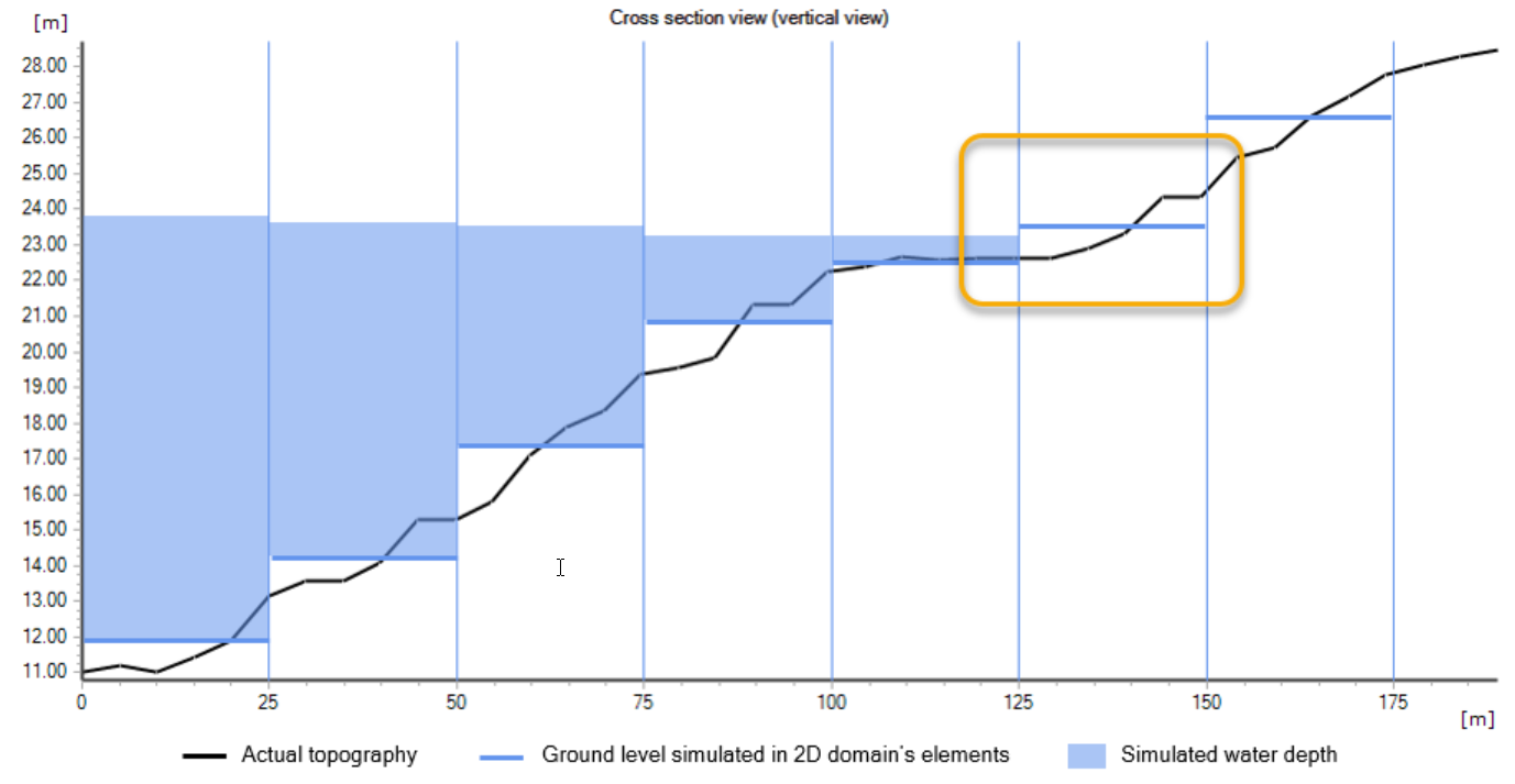
Figure: Cross section of 2D results. The mesh element in the rectangle is dry, but water level from neighboring element should be extrapolated to map water depths in the low levels of the element.
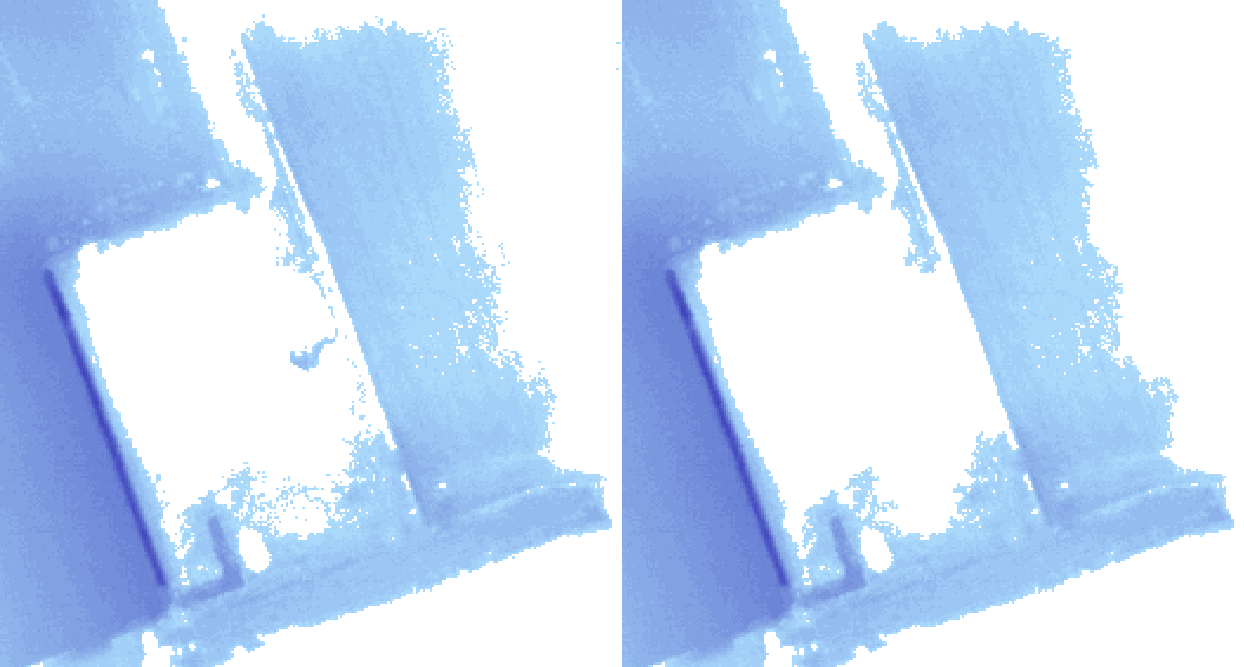
Figure: Output water depths without (left) and with (right) removal of small flooded areas
Output raster
This group holds the path and name of the output raster file. Both .tif and .dfs2 file formats are supported.
The output raster will inherit its map projection, coordinates, cell size and number of cells from the input DEM.
When the output raster is saved in .tif format, the unit of its water depth values must also be selected from the corresponding drop-down list. When it's saved in .dfs2 format, the unit is fixed and values later displayed from the file are automatically shown according to the unit system of the project.
Configuration
Once the tool has been configured, it is possible to save its configuration to a file using the 'Save…' button for later re-use. This configuration can later be loaded again using the 'Open…' button, or can be used to execute the tool from a command line.
Running the tool from command lines
MIKE+ user interface is usually the preferred way to execute this tool. However, there are times when it may be more convenient to execute the tool in an automated way without opening it in the user interface.
The MIKE+ executables enable you to execute some tools without opening their editor, through command lines. It is possible to run the 'Create flood raster' tool in this manner, assuming you have prepared the configuration file beforehand in MIKE+.
Start by locating the MIKE+ executable named DHI.MIKEPlus.ToolShell.exe in the installation folder. From a command prompt, type the command below to access the list of supported tools, replacing the … characters by the actual path to the file:
The format of the command for running the 'Create flood raster' tool is:
Where [Configuration file] is the path to the *.xml configuration file.