Demand Allocations
An alternative way to generate junction node demands can be developed based on connecting the consumption data to the appropriate nodes or pipes and aggregating their set point demand values to the junction demands. This simplifies the demand development process and allows to import consumption data from the consumption database systems and connect it to junctions based on X, Y geographical coordinates.
The 'Demand Allocations' editor is available under the 'Water demand' group in the 'Setup' tree. It is used to store and edit the consumption data defined as consumption points, so that they can be connected to the appropriate network junctions or pipes.
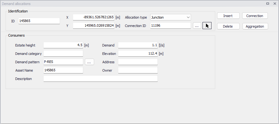
Figure: Demand allocations editor
A list of the Demand Allocations parameters follows, with a short description of each one.
- ID: This is the ID which uniquely identifies the demand point. The ID acts as a unique lookup key that identifies the demand point from all other demand points. The ID value can be any string value (up to 40 characters). It is recommended that this reference ID corresponds to the asset ID, which uniquely identifies the demand point in the customer information or billing database system.
- XY coordinates: The geographical coordinates of the demand point.
- Allocation type: This is used to specify if the connected demand is loaded to either a junction or a pipe.
- Connection ID: The ID of the junction or pipe to which the demand is connected.
- Demand: This data entry is used to specify the demand value, which will be then used in the process of the demand aggregation. This demand set point value can be imported from the external database systems (such as CIS Customer Information System, for example) or it can be developed from the minimum, average, or maximum demand values.
- Elevation: This data entry defines the elevation above a common datum for the demand allocation point, in units of feet or meters. The default value is zero.
- Estimated height: The estimated heigh is used for the computation of service pressure. The purpose of this field is to store the information used for service pressure calculation. The service pressure is commonly defined as pressure above the roof of the house or building. Hence service pressure will allow the user to store the information about such height. (In the results items this pressure will be computed as “Pressure” - “Service height”).
- Description: This field allows to enter a description identifying the consumption point defined. This description can be output in reports generated by the Report tool
- Demand Category: This data entry is used to specify the demand category such as residential, commercial, or leakage, for example. The demand category can be then used in the process of demand aggregation when demands belonging to the same junction node or a pipe are aggregated based on their demand category.
- Address: This data entry alllows you to enter an address identifying the consumption point being defined. This field can be output in the reports generated by the Report tool
- Demand Pattern: This data entry allows you to define the ID of the demand pattern to be applied to the junction node demand values during an extended period simulation. This demand pattern will be applied to the defined baseline demand. If a groundwater well is associated with this node, then a demand pattern should not be assigned—otherwise the groundwater extraction rate will be adjusted according to the assigned demand pattern. By default this data entry is blank and default demand pattern ID of 1 is assigned.
- Asset name: The optional name which uniquely identifies the demand point in the customer information or billing database system.
- Owner: This data entry allows you to enter an owner name identifying the consumption point being defined. This field can be output in reports generated by the report tool.
- Meter ID: This is a reference to a water meter ID defined in the Advanced metering infrastructure editor. This information is for use by Water Distribution Online to automatically and periodically update the hydraulic model's water demands based on the real-time telemetry data, and is therefore only used in combination with the special analysis 'Online analysis'.
Demands can be processed with the two buttons below:
- Connection: This button opens the Connection Tool, which allows to connect customer demands to model junctions.
- Aggregation: This button opens the Aggregation tool, which allows to develop total junction demands based on demand connections.