Zones
The 'Zones' editor can be used to define any type of zone. For example, pressure zones are service areas defined by the hydraulic grade-line value of the sources that supply them. A pressure zone has one or more sources of supply and may have a set of closed valves that separate it from other pressure zones.
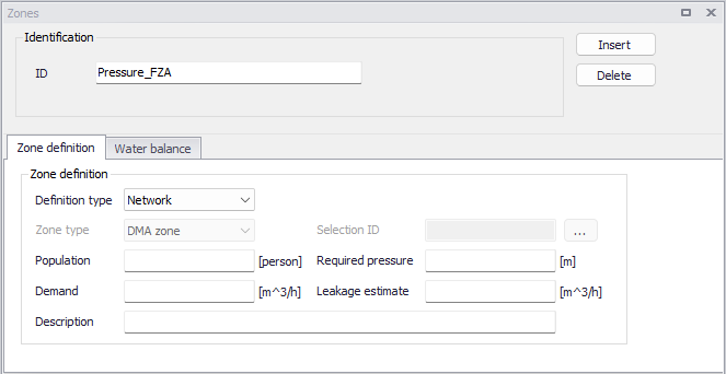
Figure: The Zones editor
New zones may be added to the list using the 'Insert' button. Zones from the list may be removed using the 'Delete' button.
Note
Deleting a zone with a 'Network' definition type will also clear the Zone ID specified for the network elements contained in this zone.
Identification
The ID is the unique identifier of the zone.
If this ID is changed for a zone with a 'Network' definition type, then the Zone ID is also updated in the properties of all the network elements contained in this zone.
Zone definition
The 'Zone definition' tab holds the following zone settings:
- Definition type: The spatial extent of zones can be defined in two different ways:
- 'Selection': with this option, the network elements (pipes, junctions, etc.) contained in the zone are listed in a selection. A given network element can belong to several zones defined by selections. 'Selection' type of zone is suitable for testing or ad-hoc purposes when performing tests.
- 'Network': with this option, the network elements defining the zone are identified by the Zone ID specified in their corresponding editors. For example, a pipe is included in a specific zone only if this Zone ID is specified in the pipe editor. A given network element can belong to only one zone defined by network properties. Network zones are synchronized with the network editors: when a new zone ID is specified for a network element, it will be listed in the list of zones; and when a zone ID is removed from all network elements, it will be removed from the list of zones. It is recommended to use automatic 'Network' type of zone for "permanent" use in the hydraulic model, when building the model or importing GIS data.
- Zone type: This is only used for zones defined by a selection. The zone type is used to identify the distributing demand by the kind of zone established. There are five types predefined in MIKE+: DMA zone, pressure zone, demand zone, region zone, ward and other.
- Selection ID: This is only used for zones defined by a selection. This data entry is used to load a previously defined selections of Network elements such as nodes and pipes for which the demand zone will be delimited. The user can create these selection lists with the selection tools.
- Demand: This data entry is used to specify the zone demand, which can be used for automatic demand distribution. To distribute the zone demand to junction nodes located within the zone, use Demand Allocation editor.
- Population: This data entry is used to specify the population per zone. It is mostly used as reference data when the user define zone demands but it has no impact on the calculated demands per zone.
- Required pressure: This field is used for the network energy calculations, presented in the log file and report from cost analyses. It is the required service pressure that is considered to be optimum for the pressure conditions within the zone. This field is used to evaluate the zone energy efficiency.
- Leakage estimate: This field is used for the network energy calculations, presented in the log file and report from cost analyses. It is the percentage of water consumption that refers to the leakage within the zone. This field is used to determine energy lost due to leakages.
- Description: This data entry allows you to enter a description identifying the pressure zone being defined. This description can be output in reports generated by the Report tool.
Water balance
The 'Water balance' tab can optionally be used to associate the zone with flow measurement stations, which can then be used to analyse the water consumption within the zone. The selected measurement stations should typically be located on the borders of the zone, in order to monitor the flow entering or leaving the zone. It can typically be used to:
- Estimate the volume consumed in the zone, as reported in this 'Water balance' tab.
- Estimate and assign the 'Demand' and 'Leakage estimate' values from the 'Zone definition' tab. This is achieved with the Compute zone demand and leakage tool.
- Create patterns of the water demand in the zone. This is achieved with the Create time patterns tool.
The 'Water balance' tab holds the following zone settings:
- Time range for water balance: This controls the time period used for all water balance computations, including for the use of the 'Compute zone demand and leakage' and 'Create time patterns' tools. Per default, the longest period covered by all flow measurements included in the zone, is used. This default period is shown at the top of the 'Time range for water balance' group. It is updated when flow measurements are added or removed from the zone. Alternatively, it is possible to restrict the period of analysis to a shorter period. To do so, activate the 'Use custom time range' option and specify the custom start and end dates to be used.
- Flow measurements: The flow measurement stations associated to the zone must be selected in this table.
- Volume balance: The 'Volume balance' value shown above the table is the estimated volume consumed in the zone, during the period of the analysis. It is computed as the sum of all volumes from measurement stations flowing into the zone, minus the sum of all volumes from measurement stations flowing out of the zone.
Note
Measurement stations are selected from the list of calibrations comparisons, defined in the 'Plots and statistics' editor. It is therefore a pre-requisite to select the measured time series in the 'Plots and statistics' editor (although no result file is needed) prior to selecting them for the zone water balance.
Click the 'Insert' button to select a measurement station to add to the zone table, from the 'Plots and statistics' list. Click the 'Delete' button to remove it from the list.
For flow measurement station, the table provides the following information and control:
- Plot ID: the ID of the plot, as specified in the 'Plots and statistics' editor.
- Unit: the unit of measured flow time series, as specified in the 'Plots and statistics' editor.
- Positive flow: this indicates whether the positive values in the time series represent water flowing into the zone or leaving out of the zone. Time series marked as "Into zone" are added to the water balance, while time series marked as "Out of zone" are subtracted from the water balance.
- Volume: this column shows the computed accumulated volume from the time series. The period used to compute this accumulated volume is the one specified in the 'Time range for water balance' group.
Note
Two types of flow measurement data can be selected in the 'Plots and statistics' editor:
- Measured discharge / flow time series, providing instantaneous values in flow units (e.g. l/s or gal/min).
- Measured volume time series, providing values of volume per time step, in volume units (e.g. liter or gallon).