Scenario Management
Water distribution and free-surface flow models are commonly used for system performance analysis and planning studies. The complexity of the involved systems, the various uncertainties about future conditions and usually huge costs associated with maintenance, rehabilitation and development necessitate a thorough investigation of alternative system configurations in a search for the technically feasible, environmentally sound and economically efficient solution.
These alternative configurations - scenarios - may differ by the system's physical layout, loading conditions, operational strategies, etc. Various projects, such as development of a Sewerage Master Plan, Wastewater Transportation Strategy, an Overflow Abatement Strategy, a River Restoration Stategy, a Flood Protection Scheme, etc. would typically result in a large number of scenarios, either representing alternative system configurations at a given time and/or representing the system at various development stages. Testing of each scenario against the prescribed legislation or the standards of service that the authorities provide requires a numerical model on its own.
These scenarios are always related to each other through the common origin ('Existing Case' or 'Base') and the differences typically encompass only a smaller part of the total data. Moreover, scenarios representing a development of the system through time are subject to the dependencies propagating along with the timeline.
Analysis of the scenarios as separate projects creates major inconveniences, such as:
- Large number of models, even when differences between them are minor.
- Missing an efficient overview over the entire set of solutions.
- Inability to maintain the existing dependencies between the individual scenarios automatically. Thus, the updating of the models with additional information requires editing of multiple files to change the same element, e.g. if a pipe diameter is found to have been incorrectly registered in the source data, it will have to be updated multiple times in each of the scenario project file.
- Unable to easily visualise differences between scenarios.
In other words, working with the scenarios as separate projects is inefficient and cumbersome.
Instead, the MIKE+ Scenario Manager provides an easy way of managing multiple scenarios, within a single MIKE+ project (i.e. a single database).
What is a Scenario Manager?
The MIKE+ Scenario Manger is accessed via the menu 'Scenarios' in the 'Setup' tree view.
The Scenario Manager enables the definition, organisation, management and reporting of alternative model scenarios, such as:
- Augmentation of existing trunk sewer mains.
- Increased wastewater loading from increased population.
- Increased water demands from increased population.
- Alternative design loads, e.g. rainfall-runoff of different return period.
- Alternative/new alignment of water, sewer and storm mains.
- Building of a new sewer trunk and water supply mains in order to cater for a new development area.
- A range of riverbed roughness values for sensitivity analysis purposes.
- Modified 2D overland roughness for land use changes impact management e.g. as a result of flooding.
- Etc.
All within the same MIKE+ project.
With the MIKE+ Scenario Manager, a user can work with an unlimited number of scenarios in a single MIKE+ project.
Design of the Scenario Manager
Data Groups, Alternatives and Scenarios
The MIKE+ Scenario Manager is based on the concept of Data Groups, Alternatives and Scenarios.
In this context, a Data Group is a set of database tables which form a meaningful set, e.g. all database tables containing collection system network data belong to the data group "CS Network Data". Every database table relevant for the scenario manager is included in one of the Data Groups.
Each Data Group in the project can have any number of Alternatives. The initial alternative is named with a default name 'Base Alternative'. Any further alternatives are created upon user request and can have a user-specified name. The Alternatives for a certain data group are organised in a tree-like structure, where dependencies propagate along the branches - from the "parent" to all the "heirs" i.e. "child" alternatives.
A scenario contains a collection of one alternative from each Data Group. Individual alternatives are used as building blocks for constructing scenarios. For example, modelling a new development area could have new alternatives for "CS Network data", “Loads and boundaries data" and "Catchments and hydrology data" data groups, while the remaining data groups remain as the base case. The moderate number of data groups allows for a manageable structure of scenarios, while ensuring a high level of flexibility.
The initial scenario is named with a default name 'Base', and consists of the 'Base' alternative of each data group. Any further scenarios are created upon user request and can have a user-specified name. The scenarios can be organised in a tree-like structure of "parents" and "children". A new scenario is created in the "Setup" menu, by a right click on a scenario (e.g. Base) and selecting "Create child scenario". Then select the new scenario in the tree and tick on the relevant alternatives for this scenario.

Figure: Create a new scenario by right-clicking on an existing scenario (e.g. Base) and selecting "Create child scenario"
Right-click on a scenario and select "Activate scenario", or click the 'Activate' button at the top of the 'Scenarios' editor, to modify the project for this collection of alternatives.
Alternatives
As described in the previous section, alternatives represent components of scenarios. The various alternatives contain the actual data belonging to a certain data group. Each subsequent alternative only contains information on the differences relative to its immediate "parent", while the rest of the data is inherited from the "parent" through the principles of inheritance.
Grouping of various alternatives belonging to different data groups into scenarios is sometimes subject to limitations, because the data groups have not been formed on the basis of data independency, but rather following the logical data grouping, recording differences according to hierarchy. E.g. An alternative of the "Catchment connections" CS data group, which specifies a catchment connection to node 'A', cannot be used with the alternative of the "Network data" data group where node 'A' has been renamed or deleted. Obviously, the catchment would remain disconnected. It is therefore prudent to plan the scenarios and alternatives before commencing a project, where possible.
Base Data vs. Child Data
When the scenario manager is activated for the first time, the system provides 'Base' alternatives for each data group automatically. The 'Base' data contains the original model database and is the "trunk" for all the alternative branches.
A 'Base' alternative for any data group can be empty, if no data are specified in any of the tables belonging to this data group. E.g. no control rule may be specified for structures, thus leaving the 'Base' alternative of the ‘Control rules data’ empty. So, although the control rules are a part of the 'Base' scenario, it does not necessarily mean that any control rule data are specified.
After making a scenario active (click the "Activate" button in the scenario manager) all the alternatives that are a part of the scenario are automatically made active and can thus be edited. Changes made to the database will be recorded within the alternative for each data group as differences to the parent alternative. If a base alternative is active for a data group, the changes made to this group will apply to this base alternative and will therefore propagate to all child scenarios.
Inheritance principles
With the inheritance from 'parent' alternatives to 'child' alternatives, some considerations must be kept in mind.
- Making a change to an alternative will affect all descendent ('child') alternatives of that alternative. This means that it will impact all the scenarios where either the alternative or the children of that alternative are applied. The benefit of this feature is that it ensures that if one value needs updating it will be updated in all the scenarios where the alternative is applied (e.g. if a pipe diameter is found to have been incorrectly registered in the GIS data during the course of a project then the pipe diameter can be changed one place only, regardless of the number of scenarios and alternatives that reference to this alternative).
- The chain of inheritance for a certain data record stops where any change (or deletion) of that element has occurred in earlier work. E.g. if a bottom level of a node 'A' has been edited in a child alternative, a later update of the bottom level in the 'Base' will only propagate through the alternative tree until it reaches the alternative containing the first change.
- Adding an element (e.g. a node) in the 'parent' with an ID that already exists in one or more of its descendants ('children') will overwrite the content of the 'child' element
- If adding an element (e.g. pump/link) in the parent that cannot be added to all the children (because some parts may have been deleted/changed there), the element is added where possible and omitted elsewhere.
Data not specific to any Alternative/Scenario
There are some data tables which are not included in the Scenario Manager.
These are typically tables containing data of general usability, i.e. data without a reference to the current network - e.g. in MIKE+ CS these include cross sections, parameter sets, etc. These data should be understood as belonging to a general project database.
There are some single record tables containing various parameters (e.g. water quality parameters) that are not part of the Scenario Manager, in order to allow the ability to apply various parameters within the same project.
The data not included in the Scenario Manager can be accessed from any scenario, regardless of the alternatives that make up that specific scenario.
Note
The computed values (derived from other fields) are not part of Scenario Manager (all fields ending with _C) and are not automatically re-computed after switching scenarios.
Managing Scenarios and Alternatives
The Scenario Manager contains two main windows:
- The 'Setup' view, showing the list of scenarios and their relationships
- The ‘Scenarios’ editor, showing the list of alternatives and their relationships, for each data group.
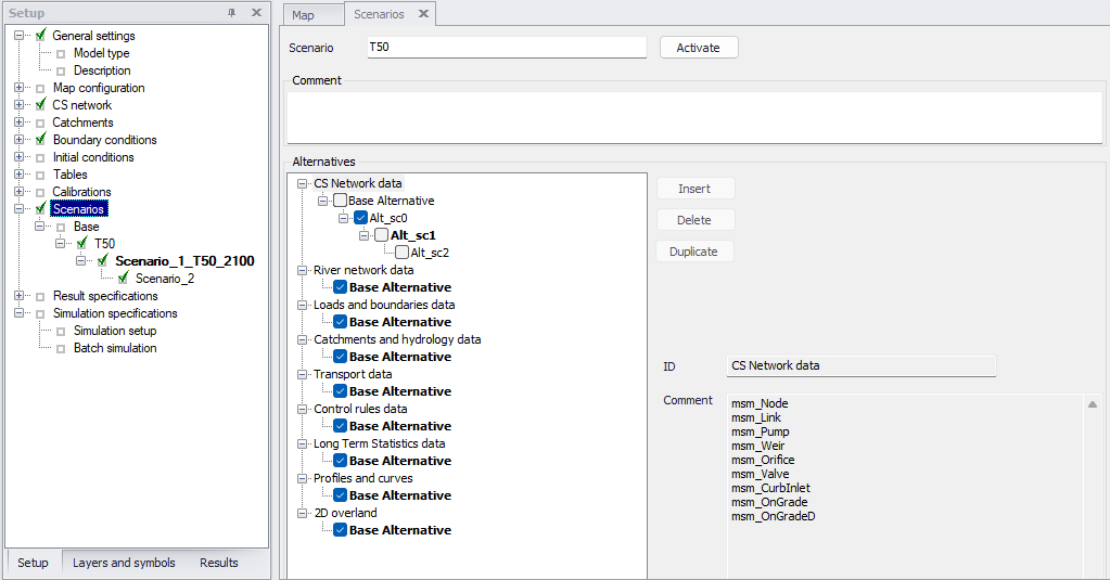
Figure: Example of the scenario window for the scenario manager - 'Scenarios' in the Setup on the left and 'Alternatives' window on the right
Scenarios
The scenario section, in the 'Setup' tree view, is used for creating, editing, and managing scenarios. Per default there will be one built-in scenario, i.e. the Base scenario. The Base scenario cannot be edited or deleted. An unlimited number of additional scenarios can then be added to cover the various 'What if' scenarios.
A mouse right-click on a scenario enables multiple actions on the scenario.
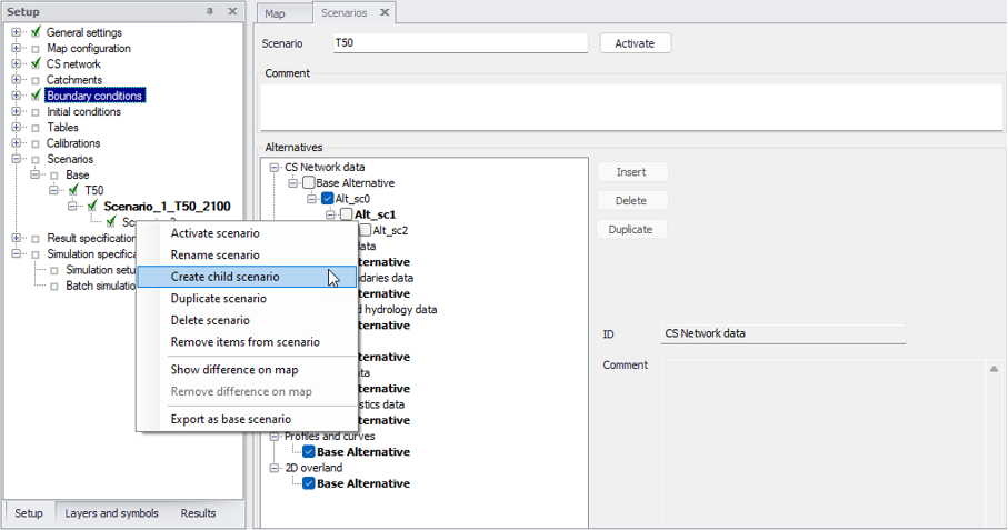
Figure: Scenario options are visible by a mouse right click on a scenario
Activate scenario
The activate scenario option will load the scenario, i.e. the project data is manipulated so that all editors contain the appropriate data corresponding to the collated alternatives for the scenario. Depending on the size of the project this may take some time.
Rename scenario
The rename scenario button will make the scenario name editable so it can be easily renamed. Alternatively, the scenario can be renamed in the Scenarios editor.
Create child scenario
The create child scenario option adds a scenario that is a child of the clicked scenario (not to be confused with the active/current scenario), i.e. to begin with, the alternatives of a new scenario will be that of the clicked scenario. A name for the new scenario is suggested by default. The name can be changed by using the rename scenario option.
Duplicate scenario
The duplicate scenario option will make a copy of the selected scenario. This means that all the alternatives that make up the original scenario will be transferred to also be applied to the new scenario. Once the new scenario has been made, the original and the duplicate scenario are edited independently of one another.
Delete scenario
The delete scenario option will remove the selected scenario. The Base scenario cannot be deleted. Note that deleting a scenario will not delete any data as the alternatives hold the data (the scenarios just refer to alternatives). The comments for the scenario being deleted, however, will also be deleted.
Remove items from scenarios
This option is used to remove the alternatives' data for some items (e.g. nodes or pipes), so that they inherit again their settings from the parent alternatives.
For example, if a pipe's diameter has been changed in an alternative, this value is no longer inherited from the parent alternative. Even if the diameter is changed again to be the same as in the parent alternative, MIKE+ still considers the two alternatives to hold different values, therefore a change of diameter in the parent alternative no longer propagates to the edited alternative. So, this option can remove this pipe diameter from the list of changes of the alternative, so that it is inherited again from the parent alternative.
Note
This function only applies to items being updated in the alternative i.e. with different attributes values than in the parent alternative. Items inserted or deleted in the alternative are not removed / restored using this function.
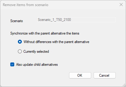
Figure: The 'Remove items from scenarios' window
This option opens the 'Remove items from scenarios' window, showing the following settings:
- Scenario: this field shows the selected scenario being updated. All alternatives (other than 'Base') used by this scenario will be analysed and possibly updated.
- Synchronization method: two options are available to control which records / items should be synchronized with the parent alternative.
- Items without differences with the parent alternative: with this method, all items which are updated in the selected scenario are compared with the parent alternative. If an item is found to have exactly the same attribute values as in its parent alternative, then this item is removed from the alternative (i.e. it becomes inherited from the parent).
- Items currently selected: with this method, all items which are currently selected are removed from the alternative (even if the selected items have different attribute values than in the parent alternative). No action is performed for items which are selected but not modified as part of the selected scenario.
- Also update child alternatives: if this option is selected, items removed from the selected scenario are also removed from the child alternatives. With the method 'Items without differences with the parent alternative', items will be removed from the child alternatives only these alternatives also have the same attributes values as their own parent. With the method 'Items currently selected', all selected items will be removed from all child alternatives.
Show difference on map
The show difference on map option is very useful to graphically display differences between scenarios. Differences are shown on the map view with a color code and will show differences between the activated scenario and the selected (right-clicked) scenario.
The color coding is as follows:
- Green: items added to the active scenario, compared to the clicked one
- Yellow: items edited in the active scenario (at least one of the item's properties has been changed)
- Red: items deleted in the active scenario, but present in the clicked one
- Others: unchanged items in the active and the clicked scenario.
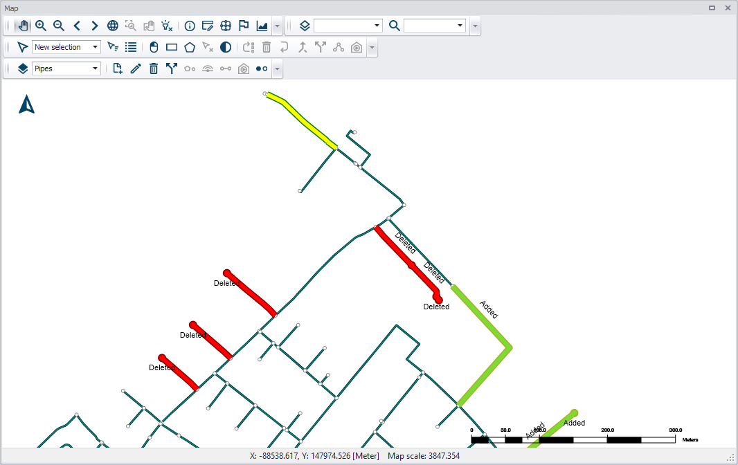
Figure: Graphical display presenting the differences between scenarios
Info
These differences can also be listed in a report. See following section for more information.
Remove difference on map
This clears the differences shown on the map.
Export as base scenario
This option creates a new database, where the clicked scenario becomes the Base scenario. This is useful e.g. in case a past scenario has become the reference situation, and it's no longer required to keep the parent scenarios.
During this operation, all children scenarios of the clicked scenario (the new Base scenario) are kept in the new database. Children alternatives are also kept even if they are not used by any of the children scenarios.
Alternatives
Alternatives can be added to the tree view in the 'Scenarios' editor regardless of the active scenario.
This 'Scenarios' editor shows the list of selected alternatives for the scenario which is highlighted (clicked) in the 'Setup' tree, which name is shown at the top of the editor (and which is not necessarily the active scenario). This selection of alternatives for a given scenario can, however, not be changed while this scenario is made active.
When a scenario is activated, the project data are manipulated so that all editors contain the appropriate data corresponding to the alternatives for the scenario.
The alternatives being currently edited (which are part of the active scenario) are displayed in bold. The name of the active alternative is also shown in the title of the editors, when it is different than the Base Alternative.
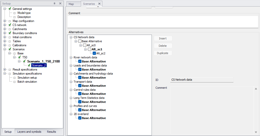
Figure: Alternatives included in the selected scenario are ticked. Alternatives currently active are shown in bold.
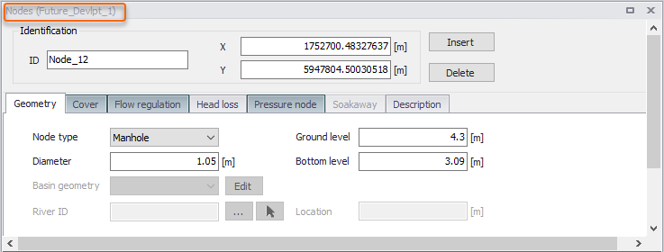
Figure: Editor showing the name of the alternative being edited
The list of tables / editors included in a given data group can be visualized by clicking on the Base alternative: the list is then shown in the 'Comment' field.
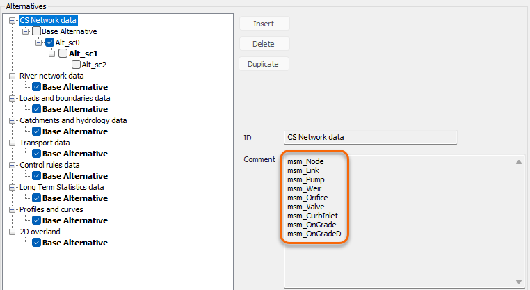
Figure: Viewing the list of tables in a selected group of alternative data
Alternatives can be defined for the following data groups:
- CS network data: this data group covers the core collection system network information, including pipes, nodes and structures. Note that cross sections for natural channels, as defined in the ‘Cross sections’ editor, are not included (see details in following list below).
- River network data: this data group covers the core river network information, including rivers, structures, storages and bed roughness. Note that cross sections are not included (see details in following list below).
- Loads and boundaries data: this data groups holds the rivers and collection system boundary conditions modelled with MIKE 1D, including boundary conditions from the 'Boundary conditions' editor, load points but also couplings to MIKE SHE.
- Catchments and hydrology data: this data group covers the core catchments definitions, the catchment connections information, hydrological model parameter sets, LID definitions and land uses.
- Transport data: this data group holds the properties for all transport processes (Advection-Dispersion, Stormwater Quality, MIKE ECO Lab, Sediment Transport).
- Control rules data: this data group contains all information defining control rules in rivers and collection system networks, including sensors, actions, control rules and PID parameter sets.
- Long Term Statistics data: this data groups contains all settings required for LTS simulations, including job list criteria, run time stop criteria, global parameters and initial conditions.
- Profiles and curves: this data groups covers tables defined in the 'Curves and relations' and 'Two-dimensional tables' editors, as well as repetitive profiles data (diurnal patterns, profile calendars, cyclic profiles and special days).
- 2D overland: this data group covers all 2D overland data except 2D boundary conditions data, as well as 1D-2D couplings. It therefore includes 2D domain definition, numerical settings, infrastructures, surface roughness, eddy viscosity, dikes, culverts, weirs, initial conditions, Advection-Dispersion settings (decay, dispersion, initial conditions), and all couplings defined in the ‘1D-2D couplings’ editor.
- 2D boundaries data: this data group covers 2D boundary conditions, 2D precipitation and evaporation, 2D infiltration, as well as their Advection-Dispersion settings (WQ boundaries, AD precipitation, AD evaporation, AD infiltration).
- Network data (SWMM): this data group covers the core collection system network information, including pipes, nodes, structures, transects, street shapes and inlets.
- Control rules data (SWMM): this data group contains the control rules definitions from the 'Controls' editor.
- Loads and boundaries data (SWMM): this data groups holds the SWMM boundary conditions, including rain gauges, dry weather flows and inflows.
- Profiles and curves (SWMM): this data group contains curves from the 'Curves and relations' editor, time series and time patterns data.
- Catchments and hydrology data (SWMM): this data group covers the core catchments definitions and their related features (aquifers, climatology, RDII hydrographs, snow packs, LID definitions and ground water).
- Transport data (SWMM): this data group holds the properties for SWMM transport processes, including pollutants, buildup and washoff on land uses, initial loading and local treatments.
- Network data (WD): this data group covers the core water distribution network information, including pipes, junctions, structures and tanks, but also zones definitions as well as regulation overview.
- Water demands: this data group contains demands defined in 'Demand allocations' and 'Multiple demands' editors.
- Control data (WD): this data group covers control rules defined in 'Real time control' and 'Extended rule-based controls' editors.
- Transport data (WD): this data group holds the properties for water quality processes, i.e. point constituent sources, trace nodes and multi-species analysis parameters.
- Patterns and curves: this data group contains patterns as well as curves from the 'Curves and relations' editor.
- Online analysis: this data group holds all data used for models used within Water Distribution Online.
Note about 2D infiltration alternatives
When infiltration is defined as spatially varying using a shape file layer, if surface roughness is also defined as spatially varying using a shape file, then the shape file must be the same, assuming that both roughness and infiltration are controlled by the same soil nature and properties. This shape file is controlled by the general ‘2D overland’ alternatives, only. It is however possible to apply alternative infiltration properties (in each polygon of the shape file) in scenarios through the ‘2D boundaries data’ alternatives.
The following list describes some of the features and settings which cannot be controlled in alternatives, and which therefore remain unchanged for all scenarios:
- Map layers: configuration of map layers is saved in the .mupp file regardless of the active scenario.
- Measurement stations, as well as Plots and statistics.
- HD and AD initial conditions for rivers and collection system networks in MIKE 1D: these initial conditions are however simulation-specific, and it is therefore possible to define different simulations in the 'Simulation setup' editor, each using a different set of initial conditions.
- Cross sections defined for rivers and natural channels: scenarios may however be defined by creating alternative cross sections in an alternative Topo ID, and referencing different Topo IDs in the rivers and pipes in the different alternatives).
- Data from 'Materials', 'Outlet head loss' and 'OnGrade capture' editors, for MIKE 1D collection system networks.
- Global parameters for rivers and collection system networks, defined in the 'MIKE 1D engine configuration' window.
- Parallelisation settings, defined in the 'Simulation' tab of the ribbon.
- Results specifications and summary files configurations.
- Simulation specifications: the configuration of simulation setups does not change with the active scenario, but instead each simulation executes one and only one scenario.
Besides the tree of alternatives, the 'Alternatives' group box contains the following buttons and fields to edit the alternatives.
Insert
The 'Insert' button adds an alternative that is a child of the selected (clicked) alternative (not to be confused with the active alternative). By a single left mouse click on the alternative, the alternative can be renamed.
Delete
The 'Delete' button will remove the highlighted alternative. The alternatives must be deleted by starting at the end of the trees until the root is reached (the alternatives can only be deleted one by one starting by the latest child). The Base alternative cannot be deleted. Remember: Deleting an alternative will delete the changes made to that alternative.
Duplicate
The 'Duplicate' button creates a copy of the selected alternative. The new copy is created as a sibling of the selected alternative, i.e. they share the same parent alternative.
Child alternatives are not duplicated.
ID
This field shows the name of the alternative being selected in the Alternatives tree. The ID can be customised for other alternatives than the Base ones.
Comment
A comment describing the selected alternative can be inserted.
Scenario Simulation
Each simulation, as defined in the 'Simulation setup' editor, is associated with a specific scenario. To be able to run a simulation for a particular scenario, it is therefore necessary to ensure that this scenario is correctly selected in the simulation to be executed.
If a new simulation has to be defined for a scenario, the typical steps to follow are:
- Activate the relevant scenario. This is done by selecting the scenario in the "setup" view, scenarios section, and then clicking the "activate" button available in the scenario manager window.
- Insert a new simulation. From the 'Simulation setup' editor, click on the "Insert" button to insert a new simulation or 'Copy' to copy an existing simulation (e.g. associated with another scenario). The active scenario will appear automatically in the "Scenario" field of the window.
- Adjust the simulation settings as necessary.
- Run the simulation. Once a simulation is created, it can be run for the Scenario ID, even when the active scenario is changed. i.e. when the simulation is run, MIKE+ will automatically activate the relevant scenario and run the model. In this way, multiple scenario simulations can be set up and run.
Example
To investigate how upsizing certain pipes and adding some real time control to the system can affect the performance of the system, start by making two child alternatives: one for the CS network data (as the pipes are a part of this group) and one for the control rules data (as the real time control is a part of that group). Then, create a scenario that applies the new CS network alternative and the new control rules data alternative and then activate this scenario.
Start editing the data in the MIKE+ tables (e.g. upsizing the pipes and adding real time control).
Once the data are edited, insert a new simulation to correspond to the active scenario. Run the model and compare the results to the original setup to see the effect of the changes.
You can also choose to make a new scenario that contains e.g. the network alternative (but not the control rules alternative), to see what change in performance the pipe upgrades alone will have.
Reporting Changes
When setting up multiple alternatives and scenarios one of the most important aspects is keeping track of the changes that have been done. The Model and Result Report tool (In the MIKE+ ribbon, select Tool |Model and Result Report) can be utilised to track and document changes made between scenarios. Refer to Chapter Reports for further details. The reports are all in XML format but can also be imported into a word document.
In the Model and Result Report tool, create a new template and select the Content to be compared Scenario section. Click "Run" to present the comparison. The table can be exported to a variety of formats. E.g. Word, Excel, *.PDF, *.XML ,etc. The report style can be utilise the default 'MUReport' format, or an imported style.
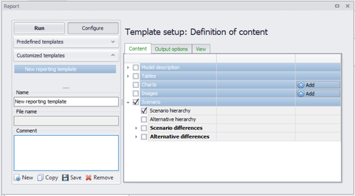
Figure: The Model and Result Reporting tool can be utilised to keep track of scenarios and alternatives
Within a report, color coding is used to signify the origin of the record:
- White - original record, no changes
- Green - record added
- Yellow - record has been changed (updated)
- Red - record has been deleted
Scenario hierarchy
Will create a table with scenario IDs, active scenario, parent of the scenario and comments.
Alternative hierarchy
Will create tables for each data group with alternative IDs, active alternative, the parent alternative, a comment, and the scenario the alternative is associated with.
Scenario differences
Scenario #1 and #2 are compared to each other, selected from a drop-down list of all the scenarios in the model. Comments in the scenario specification can be included in the comparison as an option. To narrow the comparison, specific data groups can be selected, and a choice can be made whether or not to present a comparison of everything in a report or "only include changed values that differ" between scenarios.
Alternative differences
When comparing two different alternatives, the data group to be compared must be chosen from a drop-down list of all data groups. Then two alternatives from within the specified data group can be selected to be compared to each other, selected from a drop-down list of all the alternatives within the data group. Comments in the alternative specification can be included in the comparison as an option. and a choice can be made whether or not to present a comparison of everything in a report or "only include changed values that differ" between alternatives.
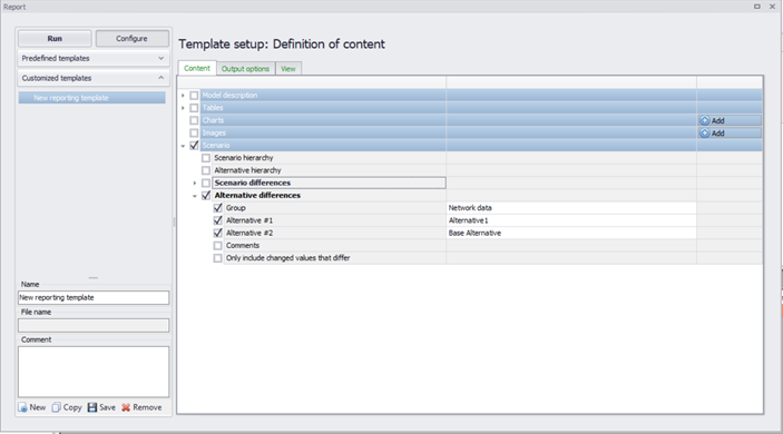
Figure: Reporting differences between Alternatives using the Model and Result reporting tool
Step-by-Step Guide to Creating a Scenario
-
In the setup view, go to the "Scenarios" editor and click on an existing scenario (e.g. 'Base') to display the editor
-
Create a child scenario by right clicking on the existing scenario (e.g. ‘Base’) and selecting 'Create child scenario'.
-
In the ‘Scenarios’ editor, select the alternative group that you wish to add an alternative to and press the 'Insert' button in the Scenario editor window
-
You can now rename it and/or continue to make alternatives
-
Once you have created the alternatives that you need, highlight the scenario you created and tick on the alternatives that you wish to include in the scenario, one for each data group;
-
Activate the scenario that you wish to work with (right click on the scenario ID in the setup view and select 'Activate scenario' or click on the 'Activate' button next to the ID of the selected scenario in the Scenario editor window). The activated scenario is displayed in bold font. Equally, all the alternatives that relate to the active scenario, are displayed in bold in the list of alternatives.
-
Edit the model, making sure to only edit the data associated with the new activated alternatives.
-
Create a new simulation for the active scenario (Simulation, Simulation setup in the ribbon view, or via the "Setup" view, Simulation, Specifications, Hydrodynamic simulation).
-
Run the new scenario and compare results to other scenarios, e.g. using the 'Compare' option in the 'Results' tree.