Dambreak
A dambreak simulates the discharge through a breach, which geometry changes in time to describe the dynamic / progressive change of the breach's geometry. The temporal description of the breach geometry may be user-defined (controlled by time series) or computed using an erosion equation.
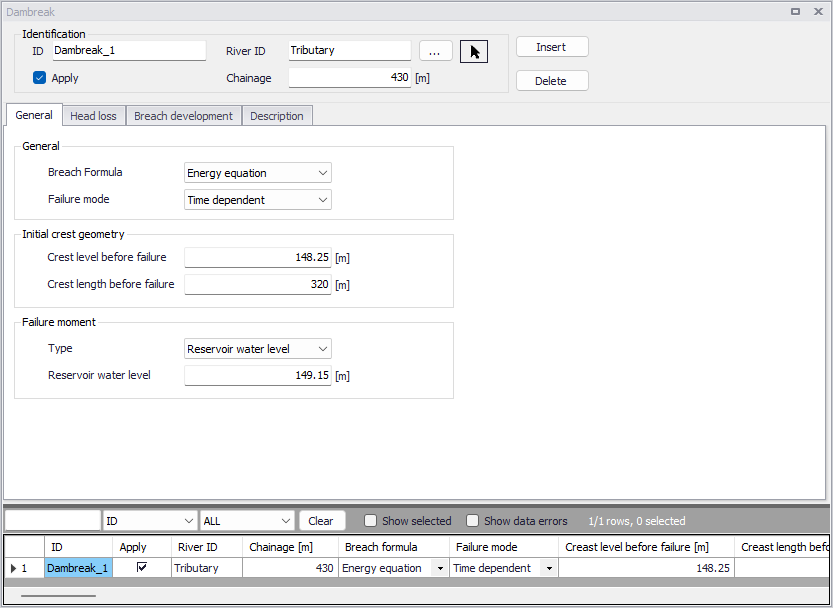
Figure: The Dambreak editor accessed via the River Network setup group
A dambreak structure is described with two structures:
- A trapezoidal weir or circular opening, describing the breach. Its geometry (bottom width, crest width, bottom level, radius, etc.) changes in time to describe the temporal development of the breach.
- A horizontal weir, describing the overflow weir at the top of the dam. Its crest length is equal to its initial length minus the top width of the breach. Before the beach starts, its length is therefore equal to the normal length before failure. When the breach starts, its length decreases as much as the breach's top width increases, so that the total length remains unchanged.
Due to the highly unsteady nature of dambreak flood propagation, it is advisable that the river topography be described as accurately as possible through the use of as many cross-sections as necessary, particularly where the cross-sections are changing rapidly.
Another consideration is that the cross-sections themselves should extend as far as the highest modelled water level, which will normally be in excess of the highest recorded flood level. If the modelled water level exceeds the highest level in the cross-section for a particular location, MIKE+ will extrapolate the processed data of the cross section.
Note on initial conditions
When performing dambreak simulations, initial conditions should be set up with care, in order to obtain relevant results. Indeed, the discharge through the breach may highly depend on the downstream water level, therefore if the breach fails early in the simulation, the results may be influenced by the initial condition. It is advised to make sure that water levels and discharge throughout the domain, just before the failure, correctly represent the expected conditions. Additionally, initial conditions may create oscillations at the beginning of the simulation, which can unexpectedly trigger the failure of the dam in case the failure moment is controlled by the upstream water level. A hotstart initial condition may be used to achieve this.
Note on product licensing
Your MIKE+ license must hold the MIKE+ Control module in order to authorize the use of dambreak structures.
Identification
The Identification group holds basic information on the dambreak.
ID
Unique string identification for the dambreak.
River ID
The ID of the river where the dambreak is located. The River ID is automatically registered if the dambreak is created via the Map. Use the button with an arrow, to select the location of the structure on the map: this will specify both the River ID and the Chainage of the structure.
Chainage
Chainage at which the dambreak is located along the river.
Apply
This check box allows the user to toggle the Active status of the dambreak on and off. The simulations will omit all dambreak structures that are not active.
General
The General tab is used for specifying the main properties of the dam and its break.
Breach formula
The calculation of the dam break may be carried out using two different formulas. These will also affect the available options for geometry and failure mode. The breach formula available are:
- Energy equation
- NWS DAMBRK equation (from US National Weather Service)
Failure mode
The development of the breach can take place in different ways. The failure mode of the structure is affected by the chosen breach formula.
When the energy equation is used to compute the dam break, the failure mode choices are:
- Time dependent. The development of the dam breach is specified by the user in terms of breach level, width and slope as functions of time (these are specified in the Breach development tab).
- Erosion based. The breach development is calculated by use of a sediment transport formula for which the parameters are specified in the Breach development tab.
If the NWS DAMBRK equation is selected the options are:
- Breach failure. The dam break initiates as a breach of the crest.
- Piping failure. The dam break initiates as a piping failure, the shape of the pipe being trapezoidal.
Crest level before failure
The initial crest level of the dam before failure.
Crest length before failure
The initial crest length (perpendicular to the flow) of the structure before failure.
The discharge through the dam is continuously computed through two separate structures, respectively describing the crest of the dam and the breach. After the failure, the width of the crest varies in time, and is equal to the Crest length before failure minus the instantaneous breach width. For this reason, the breach width cannot become longer than the Crest length before failure.
Failure moment
The moment at which the dam failure commences can be defined in the following ways:
- Hours after start. The failure is specified to take place at a specified number of hours after the start of the simulation.
- Date and time. The failure time is specified as a specific date and time.
- Reservoir water level. The failure is specified to take place when the water level in the reservoir (assumed to be at the cross section immediately upstream of the dam) exceeds the specified level.
- Control rule. This option allows to use a user-defined rule to define the failure moment. This rule is defined in the Control rules menu, and may depend on e.g. instantaneous results or external data.
Head loss
Head Loss factors
The factors determining the energy loss occurring for flow over/through the hydraulic structure. These input parameters are only required for the energy equation method and must be specified for both Positive and Negative flow.
The inflow factor is a contraction loss factor. The outflow factor is an expansion loss factor. The Free overflow factor is a calibration factor used to adjust the head loss if extra phenomena should be included (a value of 1 means that no extra head loss is added).
Flow blockage
When this option is active, the discharge computed through the dambreak is multiplied by a flow factor. This factor's value is specified in the Flow factor field. The factor is a dimensionless factor, and a value of 1 means that no change is applied to the computed discharge. A value lower than 1 can typically be used to describe the reduction of the flow through the structure due to obstacles, like debris, restricting the flow area in the structure.
Breach development
This tab contains different parameters depending on the choice made for the breach formula and failure mode.
For the Erosion based failure mode, which can be selected when the Energy equation is used as breach formula, the parameters below are used. For this case, the vertical development of the breach is calculated using the Engelund-Hansen sediment transport formula. The breach's width is determined from the product of breach depth and the side erosion index specified by the user.
Transversal dam geometry
Upstream slope
Longitudinal slope (horizontal:vertical) of the upstream face of the dam structure.
Downstream slope
Longitudinal slope (horizontal:vertical) of the downstream face of the of the dam structure.
Top width
The top width of the dam crest, in the longitudinal direction.
Material properties
Grain diameter
Representative grain diameter of the dam core material.
Specific gravity
Relative density of the dam core material. Usually ranging between 2.5 - 2.7.
Porosity
Porosity of the dam core material. Usually ranging between 0.3 - 0.5.
Critical shear stress
Critical shear stress of dam core material used for sediment transport estimation (Shields criteria). Usually ranging between 0.03 - 0.06.
Side erosion index
Multiplication factor used to calculate breach width erosion rates from breach depth predictions.
Limit of breach geometry
A limiting breach geometry must be specified using the following parameters:
- Minimum bottom level. Minimum bottom level of the trapezoidal shape describing the breach.
- Maximum bottom width. Maximum bottom width of the trapezoidal shape describing the breach.
- Maximum breach slope. Maximum transversal slope (horizontal: vertical) on the sides of the trapezoidal shape describing the breach.
Initial failure
Type of initial failure. The failure of the dam can initially take place in two ways:
- Breach failure: a breach starting at the crest of the dam
- Piping failure: a piping failure through the dam.
For the 'Breach failure' type, the additional parameters below must be specified:
- Initial level after failure. The bottom level of the trapezoidal breach at the first time step after the failure moment.
- Initial width after failure. The bottom width of the trapezoidal breach at the first time step after the failure moment.
For the Piping failure type, the additional parameters below must be specified:
- Starting level. The pipe's center level at which piping failure begins to occur.
- Initial diameter. The diameter of the piping breach at the first time step after the failure moment.
- Roughness. Pipe roughness used to calculate the Darcy friction factor.
- Collapse ratio (D/y). When the ratio between the diameter of the pipe (D) and the distance from the top of the dam to the top of the pipe (y) is larger than the collapse ratio, the pipe collapses. After it has collapsed, the breach is modelled using a trapezoidal breach.
- Volume loss ratio. When the dam collapses some of the material may be carried out without depositing on the bed of the breach. The volume loss ratio is the fraction of the material to be washed out immediately after collapse. It ranges in the interval 0 - 1.
- Calibration coefficient. Calibration multiplication factor used to adjust the calculated change in pipe radius.
Temporal description of geometry
In all the other cases, i.e. when the Energy equation is used with the 'Time dependent' failure mode, as well as when the NWS DAMBRK equation is selected as breach formula, the breach development is controlled by the parameters below.
Breach bottom level
The bottom level of the trapezoidal shape of the breach.
Breach bottom width
The bottom width of the trapezoidal shape of the breach.
Transversal slope
The transversal slope (horizontal:vertical) on both sides of the breach.
Pipe top level
Upper level of the pipe. This option is available only if NWS piping failure is selected.
All these geometry features can be defined either as constant values or as time varying ones. For the latter it is necessary to select a dfs0 file, and select the appropriate item if the file contains more than one item.
Apply limiting section
When using the Energy equation in combination with the 'Time dependent' failure mode, a limiting section can optionally be applied. If you select this option the development of the breach is limited (e.g. due to solid rock below the dam), otherwise it will be unlimited. The shape of the limitation must be specified as a cross section, in the 'Cross sections' editor. When this option is selected, the following parameters should also be specified.
River ID
Name of the river in which the limiting cross section is defined, in the 'Cross sections' editor.
Topo ID
Topo ID in which the limiting cross section is defined, in the 'Cross sections' editor.
Chainage
Chainage of the limiting cross section, in the 'Cross sections' editor.
S-coordinate of breach's center
The S-coordinate of the limiting cross section which is aligned with the breach centerline.
Description
Use the Description tab to add free text descriptions for the dambreak. It offers options for providing model management information, as well as attributes for quick model data query.
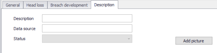
Figure: The Description tab on the Dambreak editor
- Description: Free text description for the dambreak.
- Data source: Free text describing data source for dambreak data.
- Status: Project-defined status information that may be used for model build management or e.g. model data query. Pre-defined codes are contained in the Status Code editor which may be accessed via the ellipsis button from the Status dropdown menu.
- Add picture: Option for adding images associated with the dambreak.
Dambreak s reservoir description and auxiliary structures
Dambreak's reservoir description and auxiliary structures
To obtain an accurate description of the Dam reservoir storage characteristics, the reservoir can be modelled either as a single h-point in the model or as a branch with a number of cross sections correctly defining the topography and hence, volume characteristics along the reservoir.
In case the reservoir is represented by only one h-point, this will usually also correspond to the upstream boundary of the model where inflow hydrographs are specified. The reservoir is described with a storage node, the surface storage area of the dam is described as a function of the water level. The lowest water level should be somewhere below the final breach elevation of the dam, and should be associated with some finite flooded area.