Emergency Storage Estimation
Identification
General properties for the Pump emergency storage estimation simulations are specified under the Identification group:
- ID: Unique identifier of the simulation.
- Connections: Option description of the simulation.
- Simulation ID: The selected simulation to which the pump emergency storage simulation is attached. The simulation should be created beforehand in the 'Simulation setup' editor, and can be selected using the '…'.
- Scenario: The scenario which is run by the selected simulation ID. It is here only informative, and can only be edited from the 'Simulation setup' editor.
- Start: The date and time of the start of the selected simulation. It is here only informative, and can only be edited from the 'Simulation setup' editor.
- End: The date and time of the end of the selected simulation. It is here only informative, and can only be edited from the 'Simulation setup' editor.
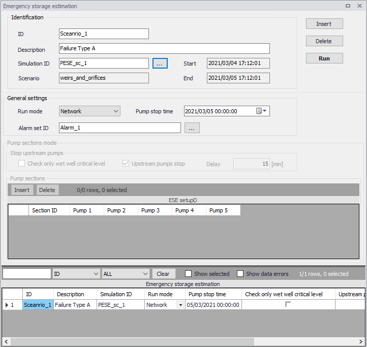
Figure: Configuring the emergency storage simulation
General settings
Pump emergency storage estimation simulations are defined by the main options below.
- Run mode: two modes are available
- Network
- Pump sections
- Pump stop time: time at which the pumps are stopped (capacity set to zero).
- Alarm set ID: The alarm set being used in the simulation is selected using the '…' button amongst the list of sets defined in the 'Alarm levels' editor.
Network
In 'Network' mode, the pump emergency storage estimation analysis is run in two automatic and consecutive simulations.
During the first simulation:
- The simulation runs under normal conditions, until the 'Pump stop time' is reached. At that time, all the pumps are stopped
- The simulation continues with the stopped pumps until alarm levels at all pumps have been exceeded, or if the simulation end time is reached
- Results of the network simulation are written to a network result file with suffix "Run1".
During the second simulation:
- The simulation starts under normal conditions as for the first simulation
- The pumped volume is recorded during the period from 'Pump stop time' until the time for reaching the specified alarm level, as simulated in the first run. This is done individually for each pump
- The simulation continues until the specified end of simulation time or until the latest time for alarm exceedance has been reached
- Results of the network simulation are written to a network result file with suffix "Run2".
Pump sections
In 'Pump sections' mode, the pump emergency storage estimation analysis is run in two automatic and consecutive simulations for each pump section. The two simulations are repeated as many times as there are pump sections specified.
The steps in the first simulation are:
- Run the simulation normally until the 'Pump stop time' is reached
- At this time, the following is done to the model for all pump stations listed in the current pump section:
- The pump is stopped (capacity set to 0)
- The first pump station in the list is identified as the "main" pump station for this analysis
- With these changes, the simulation continues until the alarm level is reached:
- If the option 'Check wet well alarm level only' is selected, the alarm level check is performed only at the wet well node for the "main" pump station (the first in the list)
- If the option 'Check wet well alarm level only' is not selected, the alarm level check is done for all pump stations in the list.
- The simulation stops once the alarm level is reached at one of the monitored points
- Results of the network simulation are written to a network result file with suffix "_PumpSectionID_Run1"
During the second simulation:
- The simulation starts under normal conditions until the user specified "Time to stop pumps" is reached
- From this time onward, the simulation continues with the identified "main" pump station active (first pump in the list). For the remaining pumps in the list there are two options available:
- If the 'Upstream pumps stop' option is not selected, all pump stations in the list are active. This is a "normal" simulation
- If the 'Upstream pumps stop' option is selected, all pump stations in the list except the "main" (first) one are stopped. The pumps are stopped with the specified 'Delay'
- The simulation continues until the time for reaching the alarm level is reached, as identified during the first simulation
- Results of the network simulation are written to a network result file with suffix "_PumpSectionID_Run2"
Pump sections mode
Options available in the 'Pump sections mode' group are only used when the run mode is set to 'Pump sections'. It comprises the following controls:
- Check only wet well critical level: Controls the alarm level check is performed only at the wet well node for the "main" pump station (the first in the list), or for all pumps in the section.
- Upstream pumps stop: Controls whether the other pumps than the main (first one) remain active or if they are stopped.
- Delay: The delay for stopping all pumps except the main one, when the 'Upstream pumps stop' option is selected.
- Pump sections table: Each row in the table adds a pumps section in the simulation. For each pumps section, it is possible to include up to five pumps in the section's list.