Sediment Fractions
Any number of individual sediment fractions can be specified (at least one). Sediment fractions are inserted and edited in the "Sediment fractions" editor.
The content of this editor changes depending on whether the basic or advanced type of simulation is selected.
Sediment fractions in basic analysis
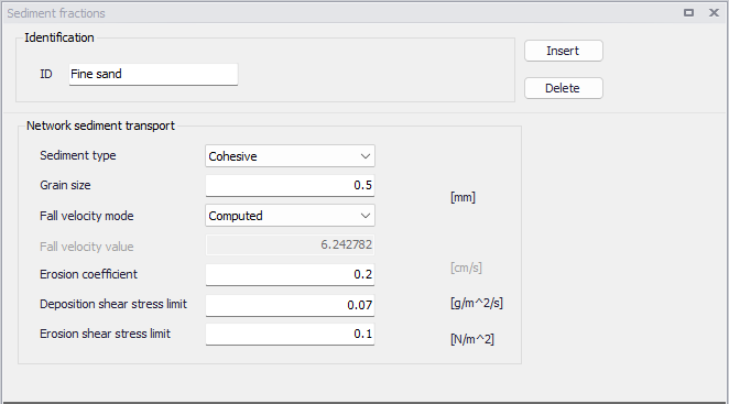
Figure: The 'Sediment fractions' editor for basic morphological anayses
Sediment fractions are defined by the following properties.
ID
Each fraction is identified by a unique name.
Sediment type
The choice between cohesive or non-cohesive fraction type is selected from this list.
Non-cohesive fractions will be described using the transport model selected in the 'General parameters' editor.
Cohesive fractions will be described by an Advection-Dispersion mechanism including a description of the erosion and deposition processes. The transport of the fine fraction (D50 less than 0.1 mm) should preferably be modelled as cohesive fractions, as the transport of particles transported in suspension is better described by used of the advection-dispersion equation. The fractions transported by the advection-dispersion module are still included in the morphological calculation, but the description of erosion/deposition is changed.
Note
The dispersion of cohesive fractions is controlled by the dispersion factors defined in the 'AD Dispersion' editor, which is accessed from the 'Water quality' group in the Setup tree.
A special type 'Fixed material' can also be selected for very coarse fractions, which are not expected to be transported during the simulation.
Grain size
The median grain size (d50) value, which is applied throughout all calculation points in the network.
Fall velocity mode
The fall velocity can either be user-defined or can automatically be computed using the Rubey formula by MIKE+. The Rubey formula computes the velocity based on sediment fraction grain size, sediment relative density and water viscosity (at 20 deg.C).
Fall velocity value
When using a user-defined fall velocity, the corresponding value is entered here. When applying the Rubey formula, this displays the automatically calculated value.
Erosion coefficient
Determines the rate of erosion when bottom shear stress exceeds the erosion shear stress limit (only for cohesive fractions).
Deposition shear stress limit
The maximum value of bottom shear stress at which sedimentation of the actual fraction will occur (only for cohesive fractions).
Erosion shear stress limit
The minimum value of bottom shear stress at which erosion of the actual fraction will occur (only for cohesive fractions).
Note
Erosion and deposition only take place in links, but not in nodes.
Sediment fractions in advanced analysis
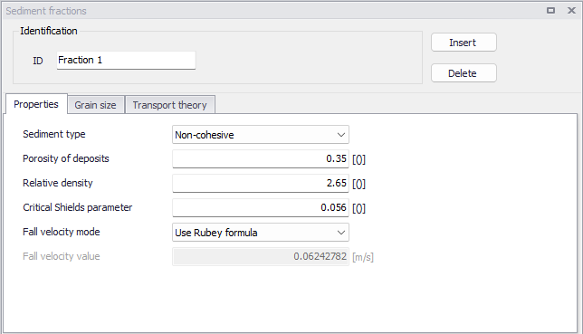
Figure: The 'Sediment fractions' editor for advanced morphological analyses
Identification
Each fraction is identified by a unique ID.
Properties
The main characteristics of the fraction are defined using the following properties.
- Sediment type: The choice between cohesive or non-cohesive fraction type is selected from this list. Non-cohesive fractions will be described using the transport model selected in the 'General parameters' editor. Cohesive fractions will be described by an Advection-Dispersion mechanism including a description of the erosion and deposition processes. The transport of the fine fraction (D50 less than 0.1 mm) should preferably be modelled as cohesive fractions, as the transport of particles transported in suspension is better described by use of the advection-dispersion equation. The fractions transported by the advection-dispersion module are still included in the morphological calculation, but the description of erosion/deposition is changed. A special type 'Fixed material' can also be selected for very coarse fractions, which are not expected to be transported during the simulation.
- Porosity of deposits: The porosity of the sediment fraction, i.e. the fraction of sediment deposits' volume filled with pores. Porosity of the bottom sediment is usually in the range of 0.3 to 0.7.
- Relative density: The density of the sediment fraction, relative to water ( solid/ water). For sand, a typical value is 2.65.
- Critical Shields parameter: The initiation of particle movement depends on the Critical Shields Parameter, \(q_{CR}\).
- Fall velocity mode: The fall velocity can either be user-defined or can automatically be computed using the Rubey formula by MIKE+. The Rubey formula computes the velocity based on sediment fraction grain size, sediment relative density and water viscosity (at 20 deg.C).
- Fall velocity value: When using a user-defined fall velocity, the corresponding value is entered here. When applying the Rubey formula, this displays the automatically calculated value.
Grain size
The grain size characteristics can be defined using the following properties.
- Default grain size: A default global grain size value, which is applied throughout all calculation points in the network, unless local values have been defined.
- Local grain size: Local grain size values can only be specified for single-fraction models, and when the fraction is non-cohesive. Local grain size values are applied at specific locations defined either as:
- List: the local grain size is applied to all links (pipes or rivers) in the selected list.
- Entire link: the local grain size is applied to the selected link.
- Point on link: the local grain size is applied to a specific point (identified by its chainage) on the selected link. The local grain size will be interpolated in space between the different points, when multiple points are defined on the same link.
Transport theory for non-cohesive fractions
The transport model for a non-cohesive fraction is defined with the following properties.
- Include: For non-cohesive fractions, it is possible to select to include in the simulation either bed load or suspended load, or both. Corresponding transport theory must be defined accordingly.
- Bed load transport model: this is the transport model for bed load transport, for non-cohesive fractions. The following models are available:
- Engelund-Hansen
- van Rijn
- Engelund-Fredsøe
- Meyer-Peter & Muller
- Adjustable Smart-Jaeggi
- Yang - sand
- Yang - gravel
- Wilcock & Crowe
- Parker
- Ackers & White
- Bed load factor: A bed load factor is applied to the selected transport formula. It is a simple multiplication factor applied to the calculated transport rate. The default neutral value is 1, and values can vary between 0.5 and 2.0. Beyond this range the validity of the chosen formula could be questioned.
- Suspended load transport model: this is the transport model for suspended load, for non-cohesive fractions. The following models are available:
- Engelund-Hansen
- van Rijn
- Engelund-Fredsøe
- Meyer-Peter & Muller
- Adjustable Smart-Jaeggi
- Yang - sand
- Yang - gravel
- Garcia & Parker
- Ackers & White
- Lane-Kalinske
- Suspended load factor: A suspended load factor is applied to the selected transport formula. It is a simple multiplication factor applied to the calculated transport rate. The default neutral value is 1, and values can vary between 0.5 and 2.0. Beyond this range the validity of the chosen formula could be questioned.
When the Adjustable Smart-Jaeggi formula is selected for a non-cohesive fraction, the following parameters are also required, for both bed load and suspended load.
- d90/d30: Describes the uniformity of sediments for the faction.
- Angle of repose: The angle of repose is specified here.
- Slope dependency: The slope dependency is either defined as a function of the bed slope or the water surface slope.
- Shields stress: The Shields stress is either defined as total or skin friction.
- Coefficients and exponents: Parameters a1 to a8 are coefficients and exponents used in the Smart-Jaeggi formula. Refer to the MIKE 1D reference manual for more detailed information.
Transport theory for cohesive fractions
The following parameters are required to describe the suspended load of cohesive fractions. Default values are applied globally throughout all calculation points in the network, unless local values have been defined. Local values are added to the secondary table, and are located by a point identified with a link ID (pipe or river ID) and a chainage along this link.
- Exponent: The exponent used in the erosion equation, from MIKE 1D reference manual.
- Erosion shear stress limit: The minimum value of bottom shear stress at which erosion of the actual fraction will occur.
- Erosion coefficient: The erosion coefficient used in the erosion equation, from MIKE 1D reference manual. It determines the rate of erosion when bottom shear stress exceeds the erosion shear stress limit.
- Deposition shear stress limit: The maximum value of bottom shear stress at which sedimentation of the actual fraction will occur.