Composite Structures
A composite structure is a combination of weirs and short culverts. It is defined as a cross section in the 2D model where total discharge across the cross section is calculated using empirical formulas for weirs and culverts and distributed along the cross section.
In the numerical calculations the cross section is defined as a section of element faces which is treated as an internal discharge boundary but the flux contribution to the continuity equation is corrected to secure mass conservation. The approach for calculating the mean water level and for distribution of the total discharge are the same as the approach used for weirs and culverts.
An example of a composite structure could be a bridge with multiple waterways. Such a structure can be described by a number of culverts, each defining an individual waterway. Additionally, for a potential bridge deck overtopping a weir can be included to describe such an overflow.
A set of structures forming a composite structure are recognised by the program from the location definitions. Locations must be completely identical for all the structures forming the composite structure. That is, the table of coordinates defining the structure locations must be exactly identical (number of coordinates and coordinate values) for all structures defined.
For more complex schematisations of structures, consider modelling the structures in 1D, coupled to 2D.
Examples of composite structures are given below.
Example 1: A wide weir with a small opening
Consider a weir as illustrated in the figure below.
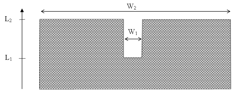
Figure: Wide weir with a small opening
There are a number of possibilities when modeling this:
- One weir
- Two weirs with width \(W_{1}\) and width \((W_{2}-W_{1})\), respectively
- Three weirs with widths \(W_{1}\) and two with width \((W_{2}-W_{1})/2\), respectively
Using the first approach is only appropriate if the weir can be contained within a single grid cell. The second approach may be used if the weir spans multiple cells, keeping in mind that the flow over the highest crest (\(L_{2}\)) is uniformly distributed over all the affected cells. The third approach will give the best representation of the flow. Note that the location needs to be defined for each of the segments for case 2 and 3.
Example 2: A wide weir with multiple culverts
Consider a structure as illustrated in the figure below.
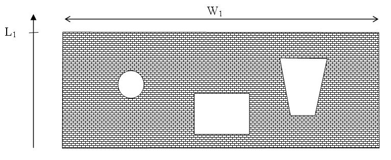
Figure: Wide weir with multiple culvert openings
The composite structure should be implemented as four separate structures:
- A weir with a constant crest level L1 and a location defined by the full extent of the weir
- A circular culvert and a location defined by the full extent of the weir
- A rectangular culvert and a location defined by the full extent of the weir
- An irregular culvert described by a level/width table and a location defined by the full extent of the weir
Note
The location needs to be defined for each of the four structure components separately. The location line should correspond to the maximum width of the structure component while still obeying the minimum requirement with respect to intersecting the line segments connecting cell centres.